Scanning probe microscope

a probe microscope and scanning technology, applied in the direction of mechanical roughness/irregularity measurement, semiconductor/solid-state device testing/measurement, instruments, etc., can solve the problem of disadvantageous detection of adhesive force, and achieve the effect of removing the artifactual effect of the prob

Inactive Publication Date: 2009-12-15
HITACHI LTD
View PDF12 Cites 11 Cited by
  • Summary
  • Abstract
  • Description
  • Claims
  • Application Information

AI Technical Summary

Benefits of technology

[0014]The present invention is provided in view of the above problems. The present invention provides a scanning probe microscope that, in acquiring a plurality of sample properties by allowing the probe to approach and withdraw from the sample, acquires at least one sample property while varying the amplitude of the withdrawal and approach depending on the magnitude of the adhesive force between the probe and the sample, to display a sample property distribution acquired for rapid and reliable detection of absorbability.
[0016]The present invention allows the probe to withdraw from and approach the sample with the minimum required amplitude instead of a constant amplitude used in the conventional art. This enables a plurality of sample properties to be measured at a high speed in the minimum required time.

Problems solved by technology

When the method described in Japanese Patent Laid-Open Publication No. 11-352135 (the probe is allowed to repeatedly withdraw from and approach each point on the sample) is used to acquire the shape of the sample and the properties of the sample other than its shape, if the adhesive force between the probe and the sample is great with respect to the vertical amplitude of the probe, the adhesive force may disadvantageously not detected.

Method used


Image

  • Scanning probe microscope
  • Scanning probe microscope
  • Scanning probe microscope

Examples


embodiment 1

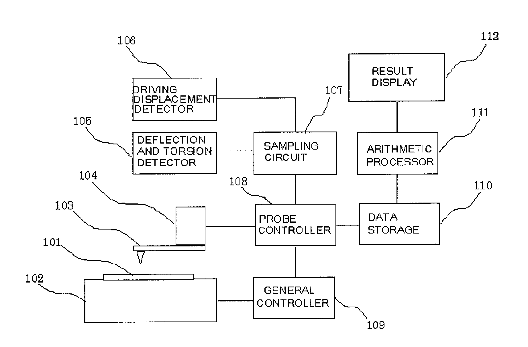
[0035]FIG. 1 shows an example of the configuration of a scanning probe microscope in accordance with Embodiment 1 of the present invention.

[0036]The device is composed of a sample stage 102 that is movable with a measurement sample 101 placed thereon, a probe 103 that scans the sample, a probe driver 104 that drives the probe in an X direction, a Y direction, and a Z direction, a deflection and torsion detector 105 that detects the deflection and torsion of the probe, a driving displacement detector 106 that detects the driving displacement of an X axis, a Y axis, and a Z axis, a sampling circuit 107 that samples each sensor signal detected, a probe controller 108 that gives instructions to the probe driver 104, a general controller 109 that controls the sample stage, measuring sequences, and the like, a data storage 110 in which data is recorded, an arithmetic processor 111 that executes an arithmetic process and the like, and a result display 112 that displays the results of proce...

embodiment 2

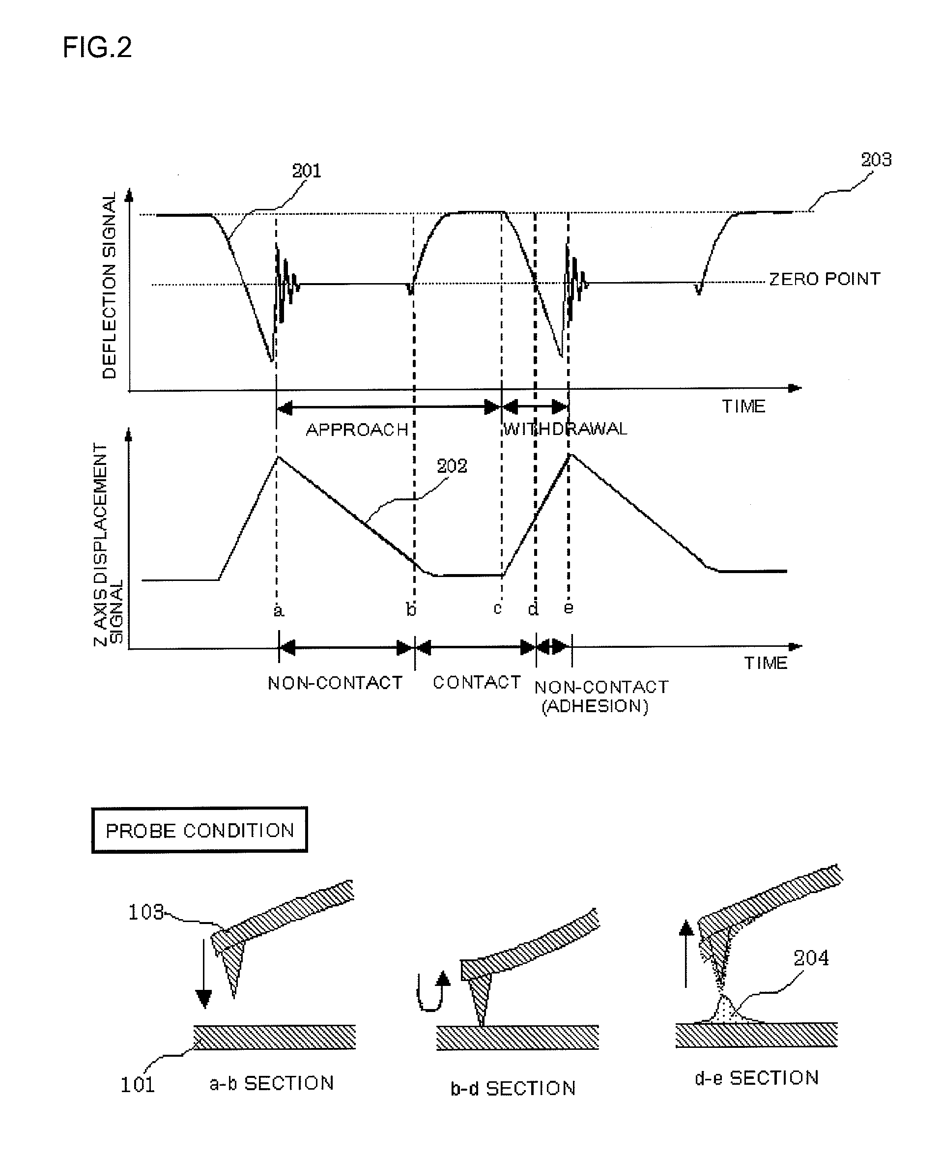
[0039]With reference to FIG. 2, description will be given of a method of calculating a sample property using a scanning scheme of allowing the probe to withdraw from and approach the sample (the scheme disclosed in Japanese Patent Laid-Open Publication No. 2001-33373).

[0040]The present scheme moves the probe perpendicularly to the sample surface with the scanning of the probe completely stopped (the speed in a scanning direction is zero). This allows a force acting perpendicularly to the sample surface to be accurately detected. FIG. 2 shows a variation in each sensor signal observed when the present scheme is used. Reference numeral 201 denotes a deflection signal indicative of a variation in the deflection angle of the probe. Reference numeral 202 denotes a Z axis variation signal indicative of a variation in the displacement of the Z axis.

[0041]In an a-b section in FIG. 2, the probe is allowed to approach the sample and is not in contact with the sample. In a b-c section in FIG. ...

embodiment 3

[0072]The operation of the probe and the timing of signal sampling will be described with reference to FIG. 9. After the probe starts to approach the sample, two thresholds 301 are set for the deflection signal. When the probe comes into contact with the sample to cause the deflection signal to exceed the given threshold (901), the deflection signal and the probe displacement signal are sampled to allow elastic force to be calculated.

[0073]When the amount by which the probe is pushed into the sample reaches a preset value (the contact force between the probe and the sample reaches a given value) (902), a probe displacement signal or a Z axis driving signal is sampled in order to calculate a shape image.

[0074]To approach the sample, the probe is moved at a constant speed until it comes into contact with the sample. After the probe comes into contact with the sample, servo control is performed using contact force.

[0075]The probe may be allowed to approach the sample only by servo cont...


PUM


Abstract

With a scanning probe microscope, if a plurality of sample properties are measured using a scanning scheme of allowing a probe to approach and withdraw from a sample, the sample properties need to be accurately and reliably detected in the minimum required measurement time. Further, the acting force between the probe and the sample varies depending on the type of the probe and the wear condition of a probe tip. Thus, disadvantageously, property values acquired using different probes cannot be compared with one another unless the artifactual effect of the measuring probes are eliminated. In accordance with the present invention, with a scanning probe microscope, the probe is brought into intermittent contact with the sample, while driving means repeatedly allows the probe to approach and withdraw from the sample with a variable amplitude. The sample property is thus acquired at a high speed. Further, a calibration sample is used in a given environment (given temperature and humidity) to acquire a force curve for at least one point. Information obtained from the force curve is used to correct measurements to display the distribution of the sample property.

Description

[0001]The present application is based on and claims priority of Japanese patent application Nos. 2006-116676 filed on Apr. 20, 2006, and 2007-063377 filed on Mar. 13, 2007, the entire contents of which are hereby incorporated by reference.BACKGROUND OF THE INVENTION[0002]1. Field of the Invention[0003]The present invention relates to a method for, in measurements using a scanning probe microscope, acquiring a plurality of sample properties to display results, and a method for evaluating a sample using the same, and to a scanning probe microscope that can acquire a plurality of sample properties to display results. Application fields of the present invention include biology, physics, semiconductors, and storages. Using the present invention for research and development in these fields enables an increase in the efficiency of the research and development.[0004]2. Description of the Related Art[0005]Scanning probe microscopes (SPM) are known as a technique for measuring micro three-di...

Claims


Application Information

Patent Timeline
Patent Type & Authority Patents(United States)
IPC IPC(8): G01B5/28G01Q60/28G01Q10/02G01Q10/06G01Q30/06G01Q60/24G01Q60/26G01Q60/38H01L21/66
CPCB82Y35/00G01Q60/28G01Q30/04G01Q10/06
Inventor BABA, SHUICHIWATANABE, MASAHIRONAKATA, TOSHIHIKOKURENUMA, TORUKURODA, HIROSHIMORIMOTO, TAKAFUMIKEMBO, YUKIOEDAMURA, MANABU
Owner HITACHI LTD
Why Eureka
Try Eureka