
Conveyor induct system

a conveyor and inductor technology, applied in the direction of conveyor control devices, conveyor parts, transportation and packaging, etc., can solve the problems of not being diverted, affecting the throughput of the conveying system, and affecting the performance of the prior, so as to improve accuracy and consistency, and the speed of the effect of speed

Active Publication Date: 2009-12-15
DEMATIC
View PDF24 Cites 28 Cited by
  • Summary
  • Abstract
  • Description
  • Claims
  • Application Information

AI Technical Summary

Benefits of technology

[0009]Accordingly, the present invention provides an improved method and apparatus for inducting articles into a conveying system. The method and apparatus allow the position of articles traveling on individual conveyors to be more accurately determined, thus aiding the accuracy and precision of the gapping process. The method and apparatus of the present invention also allow an accurate determination, rather than an assumption, to be made as to the point at which an article moving from one conveyor to another changes from having its speed controlled by the upstream conveyor to that of the downstream conveyor.
[0013]The methods and apparatuses of the present invention provide an improved induction system that allows gaps to be created between packages that are more accurate and consistent, as well as allowing the induction system to operate at higher speeds while maintaining this improved accuracy and consistency. These and other advantages of the present invention will be apparent to one skilled in the art in light of the following specification when read in conjunction with the accompanying drawings.

Problems solved by technology

First, the gapping of the articles affects the throughput of the conveying system, which is often a factor of high commercial significance.
Second, the gapping of the articles is highly important because the gapping affects the sortation functions of the conveying system.
If insufficient space is allotted, the article may contact another article while being rotated, thus causing it to enter the branch conveyor misaligned, or to not be diverted at all.
Prior art induct systems, however, have left room for improvement as to the consistency, accuracy, and speed at which at which gapping of the articles can be performed.
One reason for the less than desirable performance of prior induct systems has been the inaccuracies that result in controlling an article as it transitions from one conveyor to another.
In the past, the controlling of gaps by using multiple conveyors traveling at different speeds has resulted in inaccuracies of the created gap partially because the point at which an article switches from having its speed controlled by the upstream conveyor to the downstream conveyor has not been able to be accurately determined.
While this point is often assumed to correspond to the moment when the center of gravity of the article reaches the midpoint between the upstream and the downstream conveyors, this assumption often proves incorrect, thus leading to inaccuracies in the created gaps.
The creation of gaps in prior art conveying systems has also been inaccurate because these prior art conveying systems are not able to accurately determine the position of articles on the conveyors.
Due to measurement inaccuracies, slippage, and other factors, this calculation of the article's position on the conveyor has a significant uncertainty.
This uncertainty of the article's position on the conveyor makes controlling the created gaps in prior art induct systems difficult.

Method used


Image

  • Conveyor induct system
  • Conveyor induct system
  • Conveyor induct system

Examples


Embodiment Construction

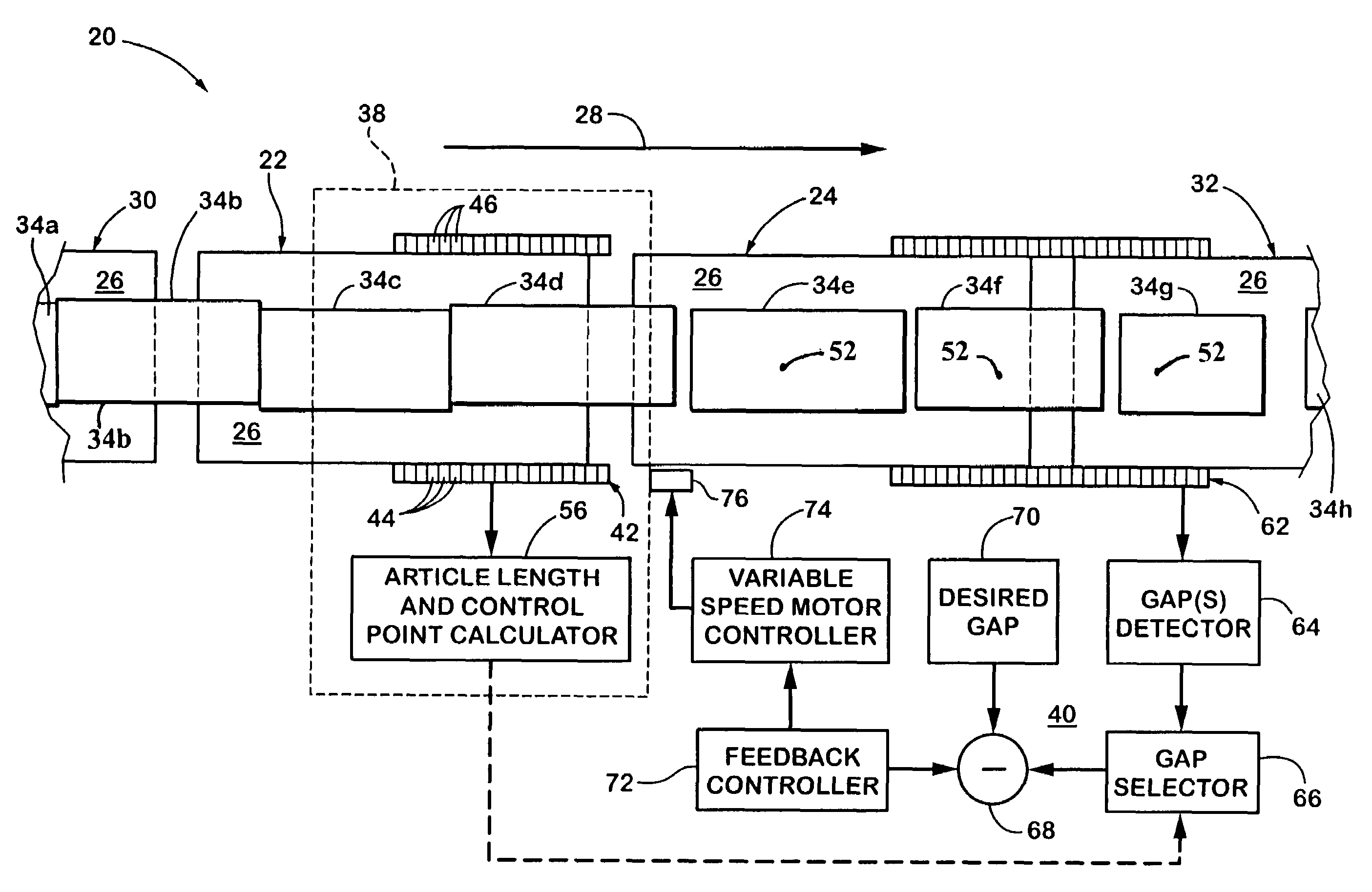
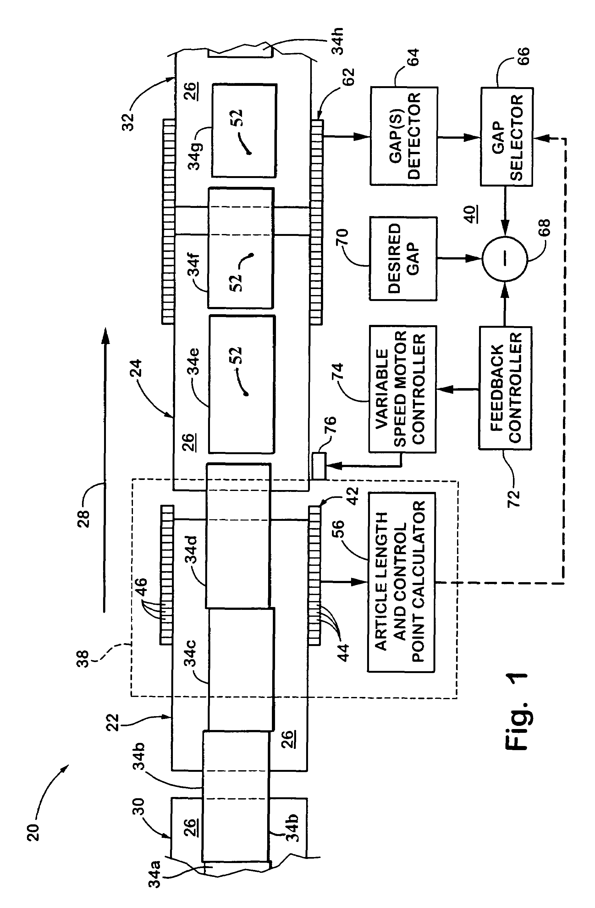
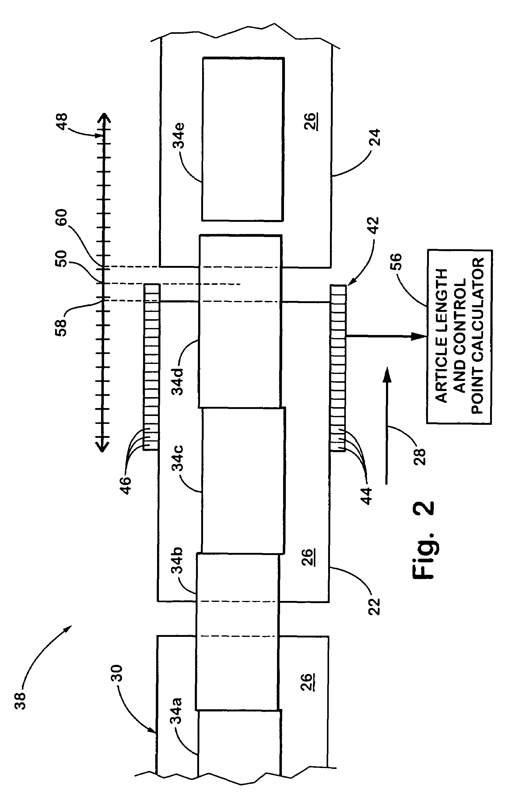
[0017]The present invention will now be described with reference to the accompanying drawings wherein like reference numerals correspond to like elements in the several drawings. A conveyor induct system 20 is generally depicted in plan and block diagram form in FIG. 1. Conveyor induct system 20 comprises two subsystems which can be utilized independently from each other or in combination with each other. One such subsystem is a control point determination module 38 which serves to accurately determine the location of the control points on individual articles, as will be explained in more detail below. The other subsystem of conveyor induct system 20 is a gap control system 40 which controls the speed of one or more of the conveyors in order to create a desired gap between articles as they exit onto a take-away conveyor 32. By way of background, such controlling of gaps is also described in commonly-owned U.S. Pat. Nos. 5,267,638 and 5,038,911, the disclosures of which are hereby in...


PUM


Abstract

A method and apparatus for controlling gaps between articles traveling on a conveyor system includes providing a plurality of tandem conveying surfaces defining a series of sequentially arranged conveying surface interfaces. At least one of the conveying surfaces associated with each of said conveying surface interfaces is an adjustable-speed conveying surface. At least one article sensor is provided adjacent at least one of the conveying surface interfaces. The article sensor provides information on positions of the articles. The speeds of the tandem conveying surfaces are controlled in a manner that establishes controlled gaps between articles, by identifying a controllable gap that can be adjusted between articles at a particular conveying surface interface and adjusting the controllable gap at the particular conveying surface interface. The control adjusts the controllable gap by adjusting the speed of the adjustable speed conveying surface associated with the particular conveying surface interface using a feedback controller. Gaps between articles are sequentially adjusted at the series of sequentially arranged conveying surface interfaces.

Description

CROSS REFERENCE TO RELATED APPLICATIONS[0001]This application is a continuation of U.S. patent application Ser. No. 09 / 851,021, filed May 8, 2001, and entitled Conveyor Induct System, now U.S. Pat. No. 6,629,593, which claims priority to commonly assigned, U.S. provisional application Ser. No. 60 / 203,301, filed May 11, 2000, and entitled Induct for Next Generation Sorter.BACKGROUND OF THE INVENTION[0002]This invention relates generally to conveyor systems, and in particular to the induction section of a conveyor sortation system. The induction section of a conveyor system generally refers to the portion of the conveying system in which articles are inducted, or initiated, into the conveying sortation system. The induction section typically performs the function of providing the proper gaps between packages, or other articles traveling on the conveying system, so that the packages can be sorted for proper distribution. The proper gapping between articles on the conveying system is im...

Claims


Application Information

Patent Timeline
Patent Type & Authority Patents(United States)
IPC IPC(8): B65G43/00B65G43/08B65G43/10B65G47/31
CPCB65G43/08B65G47/31B65G43/10
Inventor ZEITLER, DAVID W
Owner DEMATIC
Learn More