Thermal and secondary flow management of electrically driven compressors

a compressor and secondary flow technology, applied in the direction of liquid fuel engines, lighting and heating equipment, energy-saving board measures, etc., can solve the problems of increasing the manufacturing cost of the electrical motor/generator, ineffective cooling of the stator of the high-power density electrical motor/generator to the desired operating temperature, and generating a large amount of hea

Active Publication Date: 2009-12-15
HONEYWELL INT INC
View PDF17 Cites 94 Cited by
  • Summary
  • Abstract
  • Description
  • Claims
  • Application Information

AI Technical Summary

Benefits of technology

[0009]In another aspect of the present invention, a cooling system of an electrically driven compressor comprises an electrical motor, a first cooling medium circulating in a first cooling loop, a second cooling medium flowing in a second cooling loop, a heat exchange system, and a pump. The electrical motor includes a cooling jacket in direct contact with an iron stack of a stator, a stator winding having end turns, a rotor, and bearings and drives the compressor. The first cooling medium is a water based liquid coolant that travels along the cooling jacket and indirectly extracts heat from the iron stack of the stator. The first cooling loop is a closed loop. The second cooling loop is independent from the first cooling loop and is operated simultaneously to the first cooling loop. The second cooling medium is a compressed gas that extracts heat from the end turns, the rotor, and the bearings through direct contact. The heat exchange system is an external system operated independently from the generator. The first cooling medium passes through the heat exchange system. The heat exchange system cools the first cooling medium. The pump offsets any pressure loss within the first cooling loop.

Problems solved by technology

Generally, a considerable amount of heat is generated during the operation of an electrical motor or generator, and cooling the space between the rotor shaft and the stator, the rotor shaft and bearings, as well as the housing and stator, especially when the motor is operated at high speeds, is required.
While cooling a rotor with a cooling gas, such as air, may be effective for cooling a rotor, it may not be effective enough to cool a stator of a high power density electrical motor / generator to the desired operating temperatures.
This may increase the manufacturing cost of the electrical motor / generator as well as lowering the overall availability of the system due to inherent breakdown of sealing.
Wet-liquid cooling the stator may also mean that a larger gap between the rotor and the stator is needed, which may result in a lower overall motor / generator efficiency and higher losses.
Potting of end turns is not reliable since pieces can separate from the potting material and may fall into the rotating group, which can cause motor / generator seizure.

Method used


Image

  • Thermal and secondary flow management of electrically driven compressors
  • Thermal and secondary flow management of electrically driven compressors
  • Thermal and secondary flow management of electrically driven compressors

Examples


Embodiment Construction

[0015]The following detailed description is of the best currently contemplated modes of carrying out the invention. The description is not to be taken in a limiting sense, but is made merely for the purpose of illustrating the general principles of the invention, since the scope of the invention is best defined by the appended claims.

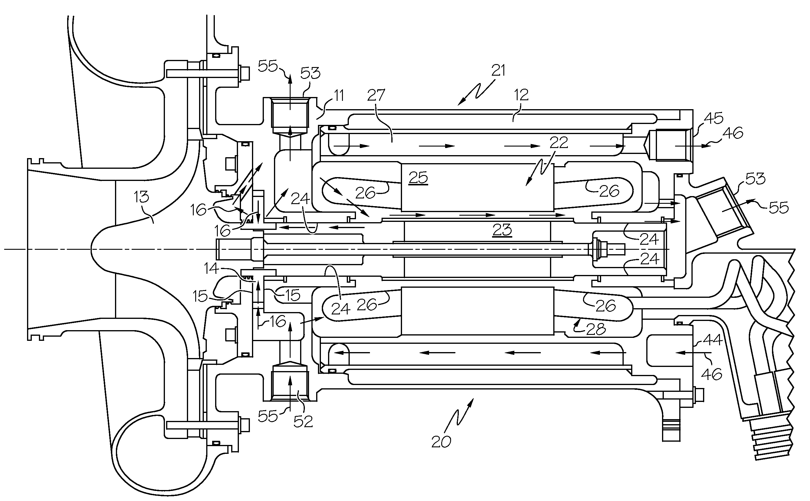
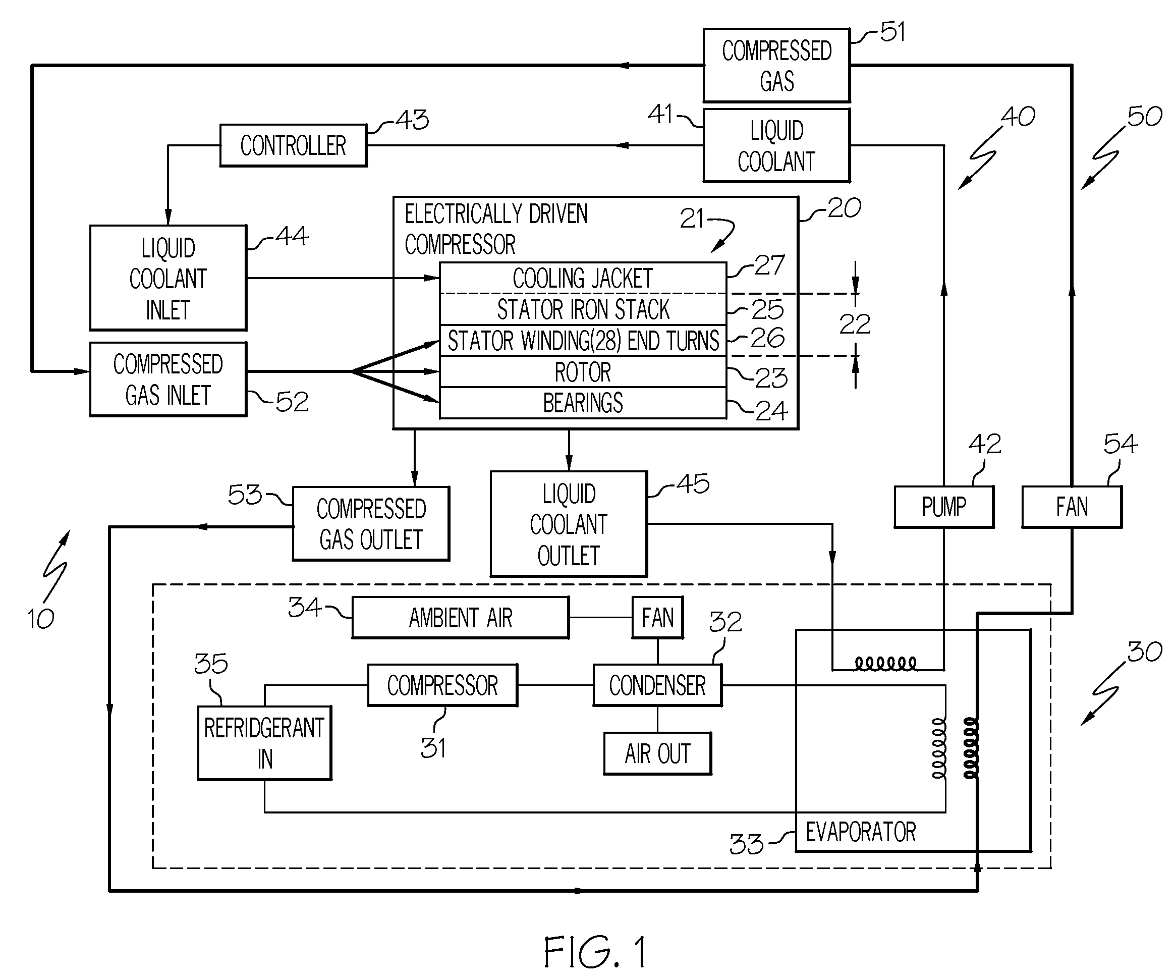
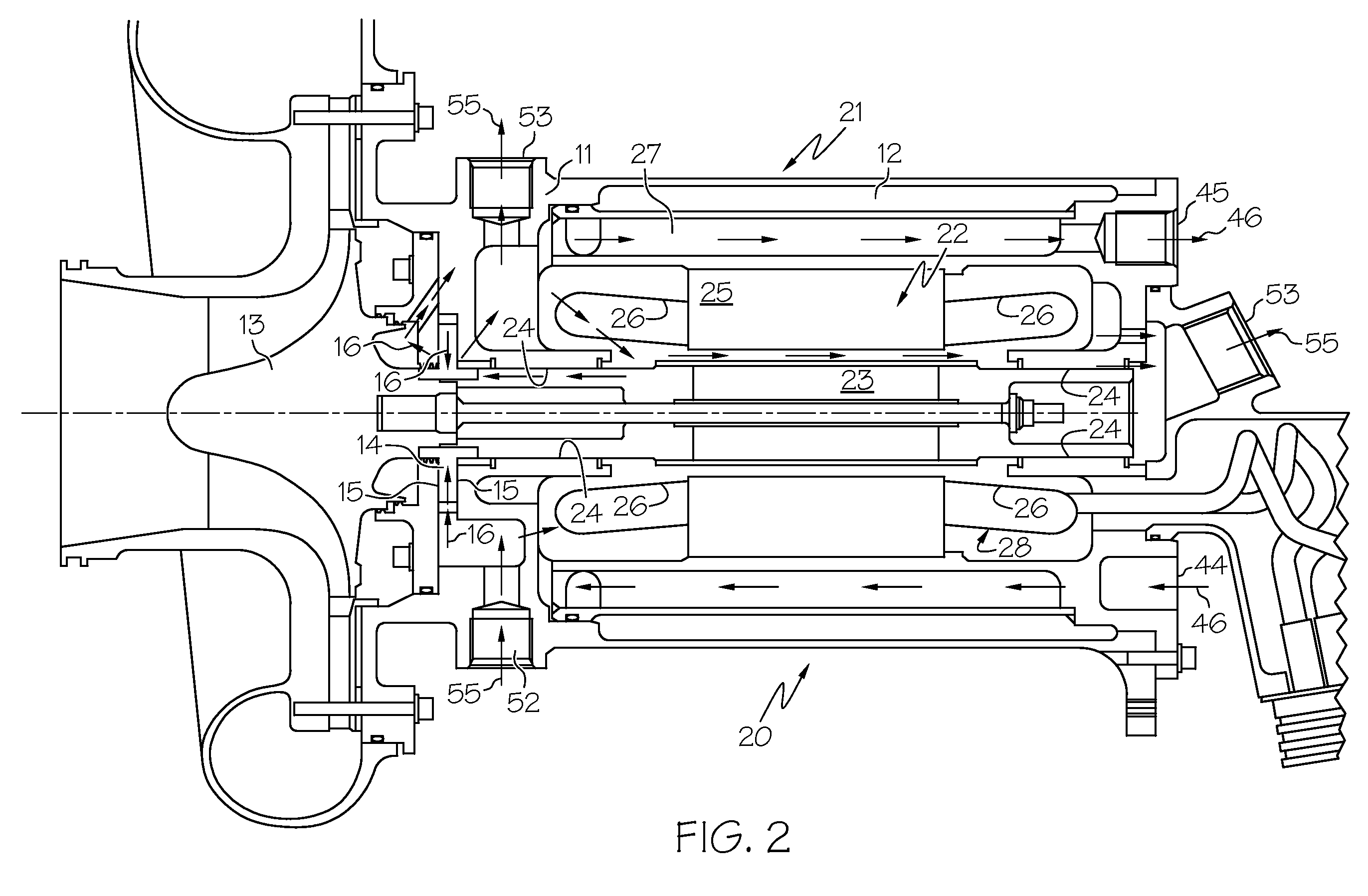
[0016]Broadly, the present invention provides a system and method for cooling an electrically driven compressor. In one embodiment the present invention provides a cooling system and method for an electrical motor or generator that is suitable for, but not limited to, applications in the aircraft and aerospace industries, such as driving a cabin air compressor of an aircraft. The cooling system and method as in one embodiment of the present invention may be suitable for, but not limited to, cooling a high speed alternating current (AC) permanent magnet electrical motor or generator running on air-foil bearings.

[0017]In contrast with the prior art, where...


PUM


Abstract

A cooling system for an electrical motor or generator includes a first cooling loop, a second cooling loop, and a heat exchange system. The first cooling loop may extract heat from an iron stack and winding of the electrical motor or generator. The second cooling loop may extract heat from end turns of the stator winding, the rotor, and the bearings independently from and simultaneously to the first cooling loop. At least the first cooling loop may pass through the heat exchange system. A liquid coolant may circulate in the first cooling loop and a compressed gas, such as compressed air or compressed refrigerant in vapor form, may circulate in the second cooling loop. The cooling system and method for an electrical motor or generator may be suitable for, but not limited to, applications in the aircraft and aerospace industries, such as driving a cabin air compressor of an aircraft.

Description

BACKGROUND OF THE INVENTION[0001]The present invention generally relates to electrically driven compressors and to the cooling of electrical motor / generators and, more particularly, to a system and method for optimized thermal and secondary flow management of electrically driven compressors.[0002]Commercial jet aircraft fly at very high altitudes, and therefore, their cabin air systems must provide a safe, comfortable, and pressurized environment. Modern aircraft are often equipped with an environmental control system (ECS) where the fresh air for the cabin is provided by electrical motor-driven compressors in place of traditional engine bleed air. Cabin air compressors have a wide operating envelop. In order to have a reliable and long lasting system, it is essential to have a thermally stable components; this applies in particular to the electrical stator and rotor as well as the bearings. Generally, a considerable amount of heat is generated during the operation of an electrical ...

Claims


Application Information

Patent Timeline
Patent Type & Authority Patents(United States)
IPC IPC(8): H02K9/00
CPCH02K9/19B64D2013/0644Y02T50/56F04D25/06F04D29/5806Y02T50/50H02K9/197H02K5/203
Inventor MASOUDIPOUR, MIKE M.LOTTERMAN, JEFF A.OXIMBERG, CAROL A.YANG, MICHAEL S.
Owner HONEYWELL INT INC
Why Eureka
Try Eureka