Liquid crystal glare-proof mirror

a technology of glare-proof mirrors and liquid crystals, applied in the direction of optical viewing, instruments, vehicle components, etc., can solve problems such as dark screens, and achieve the effect of low optical transmission loss

Active Publication Date: 2009-12-15
MURAKAMI CORP
View PDF10 Cites 127 Cited by
  • Summary
  • Abstract
  • Description
  • Claims
  • Application Information

AI Technical Summary

Benefits of technology

[0007]An object of the present invention is to provide a liquid crystal glare-proof mirror which enables to display a bright screen by allowing light to propagate through an optical system having low optical transmission loss.

Problems solved by technology

The liquid crystal glare-proof mirror disclosed in Unexamined Patent Publication (Kokai) No. 03-243914 employs a half mirror, and there has been a problem that the screen is dark when a picture is displayed because the half mirror only transmits or reflects about half of incident light.

Method used


Image

  • Liquid crystal glare-proof mirror
  • Liquid crystal glare-proof mirror
  • Liquid crystal glare-proof mirror

Examples


example 1

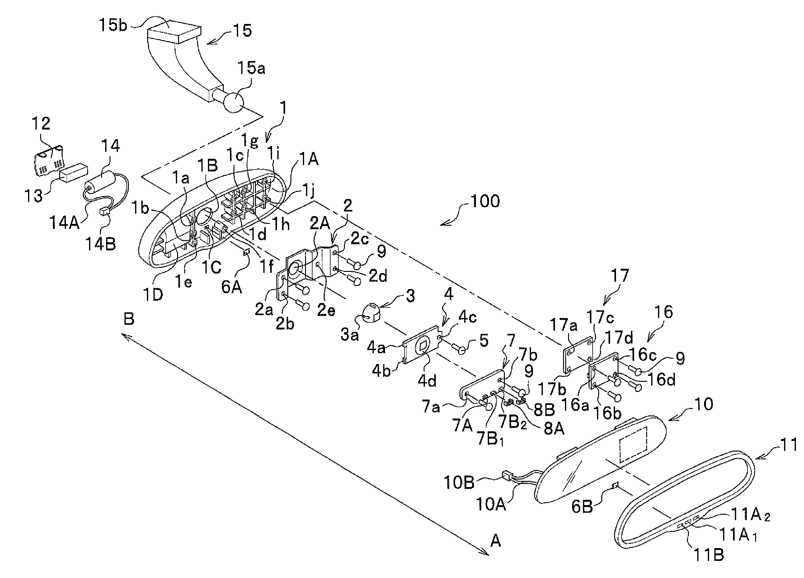
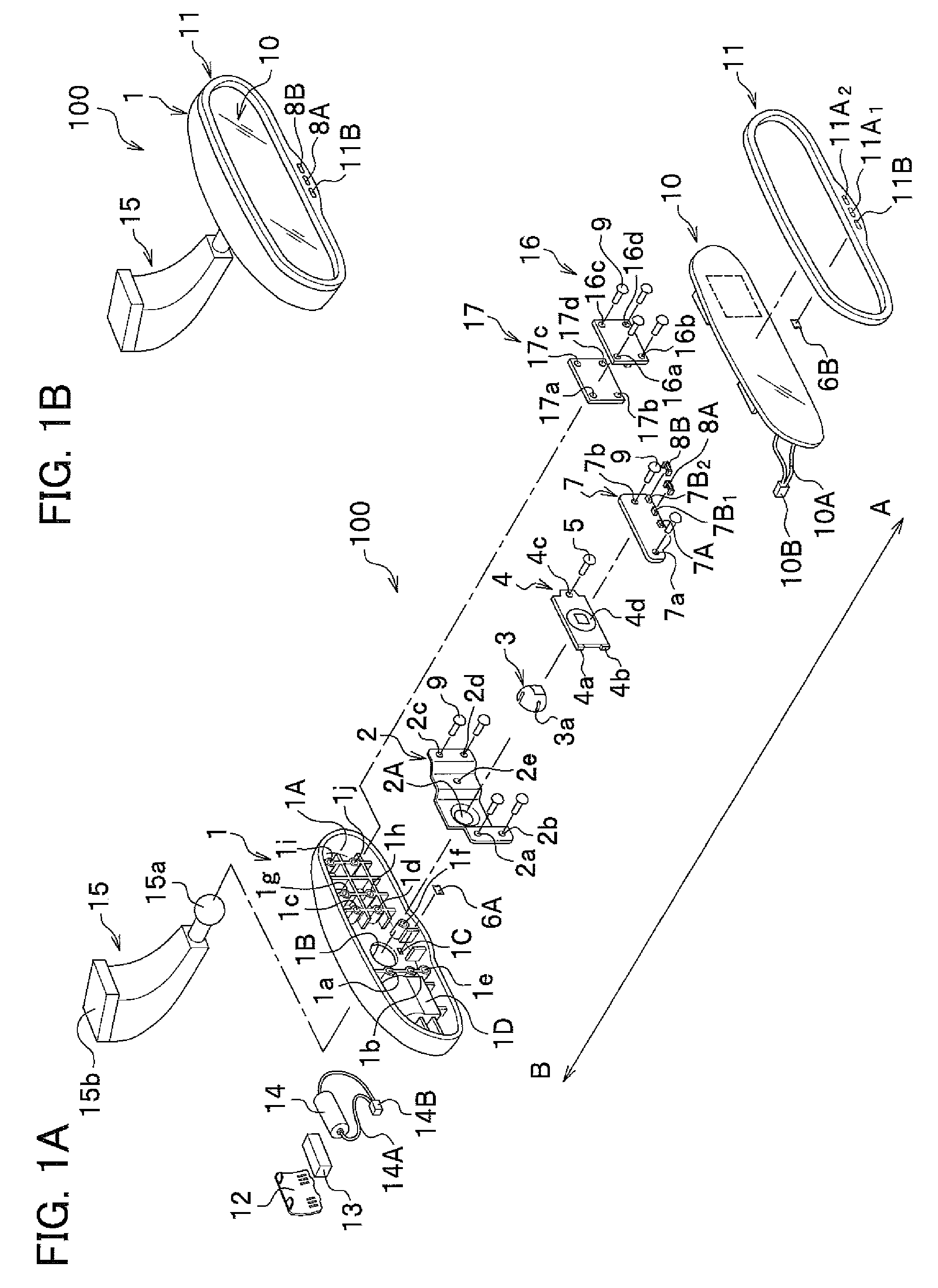
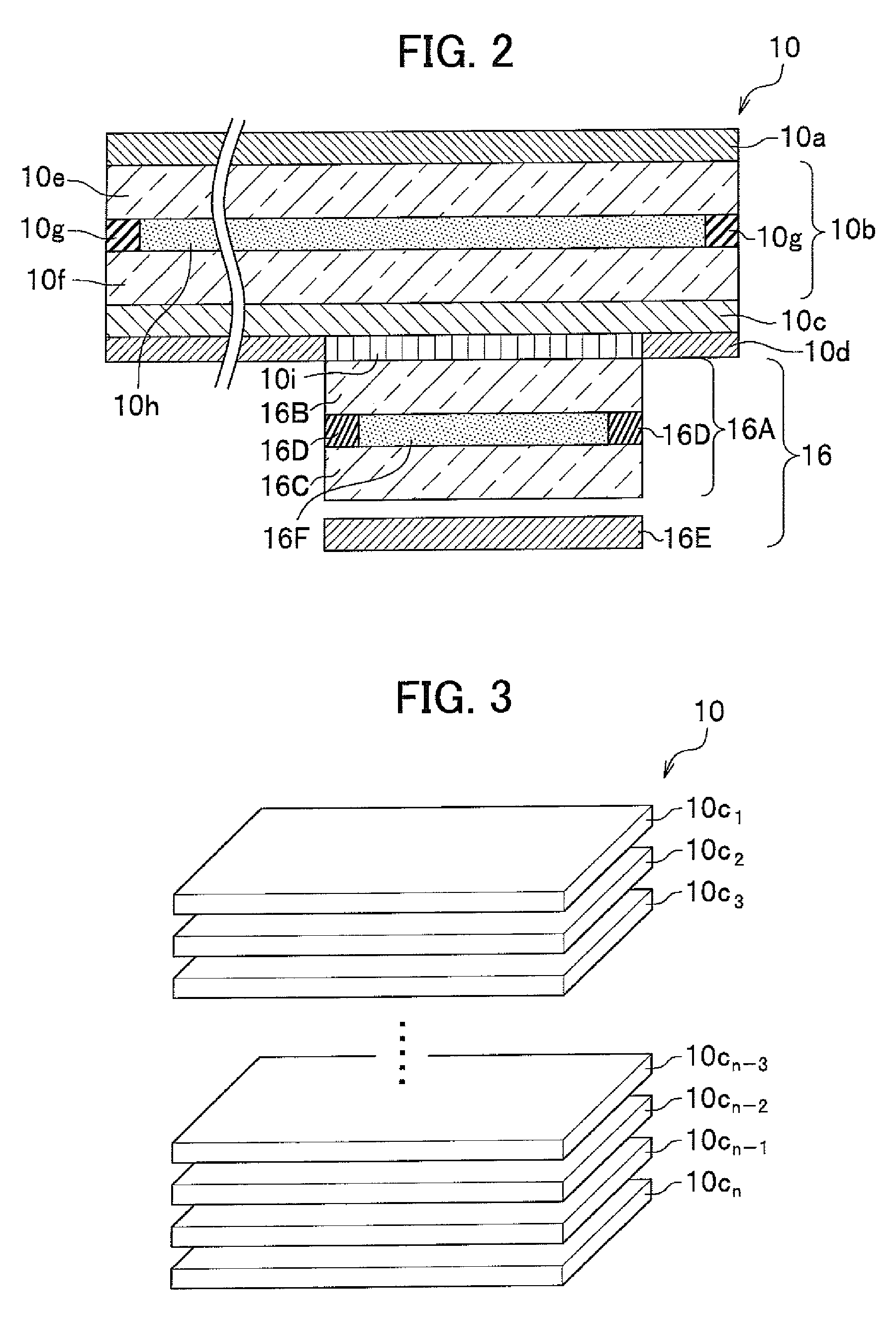
[0074]The positive electrode of a direct current power supply of which an end is grounded is connected to a switch S1 and a switch S2 via a branch point J1 as shown in FIG. 8. Connected to the switch S1 via a branch point J2 are a branch point J53 and a resistance R1. Connected to the switch S2 via a branch point J52 are an input terminal of a circuit OR1 and an input terminal A of a LSI. The LSI controls the liquid crystal cell 16A and the back light 16E. Terminals of a liquid crystal cell 16A are connected to an output terminal B and an output terminal C of the LSI. The back light 16E is connected to an output terminal D of the LSI. When the switch S2 is on, on receiving input from the input terminal A, the LSI applies voltage to the output terminal B and the output terminal C to set the optical transmission rate of each pixel in the liquid crystal cell 16A according to picture data input by an input terminal F, lights the back light 16E and makes the liquid crystal cell 16A to ej...

example 2

[0093]Similarly to the example 1, in the example 2 the positive electrode of the direct current power supply E of which an end is grounded is connected to the switch S1 and the switch S2 via the branch point J1 as shown in FIG. 9. Connected to the positive electrode of the power supply E is the resistance R1. Connected via the branch point J52 to the switch S2 is the input terminal of the circuit OR1 and the input terminal A of the LSI. The LSI controls the operation of the liquid crystal cell 16A and the back light 16E. Terminals of the liquid crystal cell 16A are connected to the output terminal B and the output terminal C of the LSI. The back light 16E is connected to the output terminal D of the LSI. When the switch S2 is on, on receiving input of the input terminal A, the LSI applies alternating voltage to the output terminal B and the output terminal C to set the optical transmission rate of each pixel in the liquid crystal cell 16A according to picture data input by the input...

modification 1

[0105]In the above embodiments, the liquid crystal glare-proof mirror 100 includes both of the surrounding light sensor 7C and the backward light sensor 7A, however, the liquid crystal glare-proof mirror 100 may include at least one of them.


PUM

PropertyMeasurementUnit
optical absorptionaaaaaaaaaa
optical transmission lossaaaaaaaaaa
internal structuresaaaaaaaaaa

Abstract

A liquid crystal glare-proof mirror is capable of displaying a picture in which a non-glare-proof mode and a glare-proof mode is switched, including a first polarizing plate for selecting a polarization component to be transmitted; a liquid crystal cell disposed at a back of the first polarizing plate, the liquid crystal cell having two control areas, each of which is controlled independently; a second polarizing plate disposed at a back of the liquid crystal cell, the second polarizing plate transmitting either one of two orthogonal polarization components of light and reflecting the other one of the polarization components; and an image generating apparatus disposed at a part of a back of the second polarizing plate, the part corresponding to either one of the two control areas, the image generating apparatus ejecting picture light having a polarization component which is transmitted through the second polarizing plate.

Description

CROSS REFERENCE TO RELATED APPLICATIONS[0001]This application claims the foreign priority benefit under 35 U.S.C. §119 of Japanese Patent Application No. 2007-170101 filed on Jun. 28, 2007, the disclosure of which is incorporated herein by reference.BACKGROUND OF THE INVENTION[0002]1. Field of the Invention[0003]The present invention relates to a liquid crystal glare-proof mirror used for an inner mirror or an outer mirror of a vehicle, for example.[0004]2. Description of the Related Art[0005]Conventionally, a liquid crystal glare-proof mirror including, for example, a liquid crystal cell having electrodes for forming picture elements, a half mirror disposed at the back of the liquid crystal cell, a back light disposed at the back of the half mirror and means for driving the electrodes in the liquid crystal cell (as disclosed in Unexamined Patent Publication (Kokai) No. 03-243914) has been known.[0006]The liquid crystal glare-proof mirror disclosed in Unexamined Patent Publication (...

Claims


Application Information

Patent Timeline
Patent Type & Authority Patents(United States)
IPC IPC(8): G02F1/1335
CPCB60R1/04B60R1/088G02F1/13318B60R2001/1253B60R2001/1215G02F1/133536G02F1/13471G02F1/133557
Inventor YAMADA, AYAKOMOTOMIYA, MASAHIROSATO, HIDENORI
Owner MURAKAMI CORP
Why Eureka
Try Eureka