Optical waveguide and manufacturing method thereof

a technology of optical waveguides and manufacturing methods, applied in the direction of optical waveguide light guides, optical fibres with multilayer cores/claddings, instruments, etc., can solve the problems of complex work to produce such optical waveguides, deterioration of optical transmission losses, etc., to reduce the spread of light signals, reduce optical transmission losses, and achieve efficient production

Inactive Publication Date: 2017-01-12
RESONAC CORPORATION
View PDF1 Cites 0 Cited by
  • Summary
  • Abstract
  • Description
  • Claims
  • Application Information

AI Technical Summary

Benefits of technology

The present invention is about an optical waveguide that can transmit light regardless of the type of substrate it is placed on. It also suppresses the reflection of light from mirrors, and allows for low optical loss. Additionally, the method described in this patent allows for the efficient production of this optical waveguide with excellent features.

Problems solved by technology

Furthermore, when a space exists between the substrate and an optical device, the spot diameter of a light signal with an optical path changed by the mirror increases, causing the optical transmission loss to deteriorate.
However, the work to produce such an optical wave guide is complicated because the component for changing an optical path is required to be inserted in each optical path changing part of the optical waveguide.

Method used


Image

  • Optical waveguide and manufacturing method thereof
  • Optical waveguide and manufacturing method thereof
  • Optical waveguide and manufacturing method thereof

Examples


example 1

Preparation of Resin Film for Forming a Clad Layer

Preparation of Base Polymer (A): (Meth)Acrylic Polymer (A-1)

[0180]46 parts by mass of propylene glycol monomethyl ether acetate and 23 parts by mass of methyl lactate were weighed and placed in a flask equipped with an agitator, a condenser, a gas introduction tube, a dropping funnel and a thermometer, and stirred with nitrogen gas introduced therein. The liquid temperature was increased to 65° C. Subsequently, a mixture of 47 parts by mass of methyl methacrylate, 33 parts by mass of butyl acrylate, 16 parts by mass of 2-hydroxyethyl methacrylate, 14 parts by mass of methacrylic acid, 3 parts by mass of 2,2′-azobis(2,4-dimethylvaleronitrile), 46 parts by mass of propylene glycol monomethyl ether acetate and 23 parts by mass of methyl lactate was added dropwise for 3 hours and stirred at 65° C. for 3 hours, then at 95° C. for 1 hour to obtain the (meth)acrylic polymer (A-1) solution (solid content: 45 mass %).

Measurement of Weight Ave...

example 2

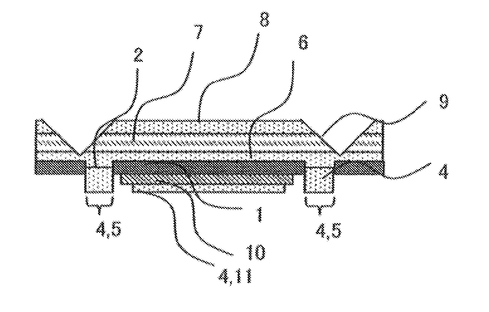
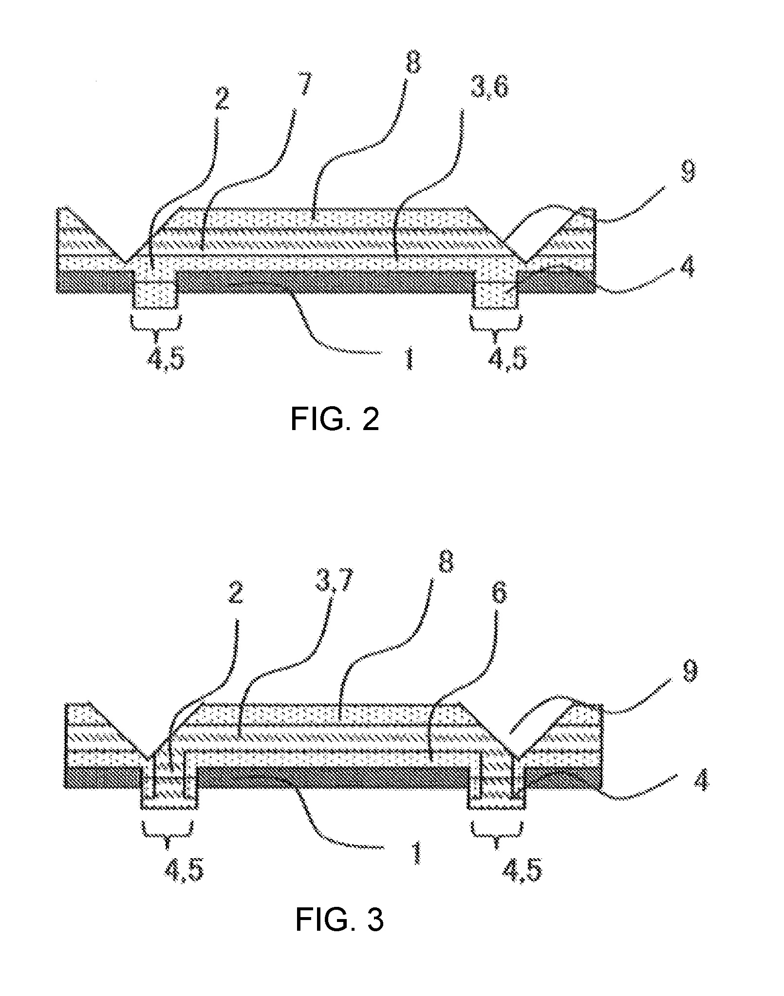
[0199]Except for using a transparent resin layer 3 with a thickness of 25 μm as the lower clad layer 6, an optical waveguide with a mirror was prepared in the same manner as Example 1 (see FIG. 2).

[0200]The total optical transmission loss of the two mirrors of the obtained optical waveguide was 2.00 dB.

example 3

[0201]In Example 2, the resin film for forming a clad layer with a thickness of 15 μm was used as the transparent resin layer 4. Ultraviolet rays (wavelength: 365 nm) were delivered at a light intensity of 0.3 J / cm2 through the negative photomask with the respective centers of the openings (80 μm) as the light shielding parts to expose the transparent resin layer 3 combined with the lower clad layer 6 and the transparent resin layer 4. After the respective centers of the openings were etched, the laminated body was washed with water, irradiated with ultraviolet rays at a light intensity of 3.0 J / cm2 from the lower clad layer 6 side with the above-mentioned exposure machine, and dried and cured by heating at 170° C. for 1 hour.

[0202]Then, a resin film for forming a core layer from which the protective film was removed was laminated to the lower clad layer. A resin film for forming a core layer with a thickness of 25 μm which is the same as that described above was laminated to the ba...


PUM


Abstract

The optical waveguide includes: a lower clad layer, a core layer, an upper clad layer, a substrate, and a mirror, the lower clad layer, the core layer, and the upper clad layer being sequentially laminated to the substrate, the mirror being formed on the core layer, in which the substrate has an opening, the maximum diameter of the opening is larger than that of luminous flux reflected by the mirror, and the maximum diameter of the opening is 240 μm or less. The optical waveguide is capable of transmitting a light signal regardless of the type of the substrate, suppressing the spread of a light signal reflected from the mirror, and transmitting a light signal with a low optical transmission loss.

Description

CROSS-REFERENCE TO RELATED APPLICATIONS[0001]This application is a continuation of application Ser. No. 14 / 371,591, filed Jul. 10, 2014, which is a 371 national stage entry of PCT / JP2012 / 084139, filed Dec. 28, 2012, which claims priority of Japanese patent application no. 2012-003590, filed Jan. 11, 2012, Japanese patent application no. 2012-003592 filed Jan. 11, 2012, Japanese patent application no. 2012-003587 filed Jan. 11, 2012, and Japanese patent application no. 2012-003589 filed Jan. 11, 2012, the contents of each of which is incorporated herein in its entirety.TECHNICAL FIELD[0002]The present invention relates to an optical waveguide and a method of producing the same. Particularly, the present invention relates to an optical waveguide with a mirror and a method of producing the same.BACKGROUND ART[0003]As information capacity increases, in not only the communication field including a trunk line and an access system but also information processing in a router and a server, t...

Claims


Application Information

Patent Timeline
Patent Type & Authority Applications(United States)
IPC IPC(8): G02B6/122G02B6/138
CPCG02B6/122G02B2006/12104G02B6/138G02B6/1221G02B6/036G02B6/13G02B6/136G02B6/43G02B2006/12166
Inventor SAKAI, DAICHIKURODA, TOSHIHIROBETSUI, HIROSHISEGAWA, KOUTAUCHIGASAKI, MASAO
Owner RESONAC CORPORATION
Why Eureka
Try Eureka