
Low scattering silica glass and method for heat-treating silica glass

a silica glass and low scattering technology, applied in glass making apparatus, glass shaping apparatus, glass making tools, etc., to achieve the effects of low optical transmission loss, high fictive temperature, and low scattering coefficien

Active Publication Date: 2016-06-02
ASAHI GLASS CO LTD
View PDF2 Cites 5 Cited by
  • Summary
  • Abstract
  • Description
  • Claims
  • Application Information

AI Technical Summary

Benefits of technology

The present invention relates to a new type of silica glass with low Rayleigh scattering coefficient, which can be used to make optical communication fibers with low transmission loss. The invention also provides a method for heat-treating silica glass to obtain high quality glass with low scattering coefficient. The glass has minimal amounts of certain structures that can be caused by ultraviolet rays, which makes it suitable for use in optical devices that require high transparency. The method allows for efficient production of the low scattering glass, while minimizing coloration.

Problems solved by technology

Transmission loss of an optical fiber has a significant impact on the performance of the optical communication network.

Method used


Image

  • Low scattering silica glass and method for heat-treating silica glass
  • Low scattering silica glass and method for heat-treating silica glass

Examples


examples

[0084]Now, the present invention will be described in further detail with reference to Examples. However, it should be understood that the present invention is by no means restricted thereto.

[0085]Ex. 1 to 3, 6 to 8 and 14 are Examples of the glass of the present invention, and Ex. 4 to 5 and 9 to 13 are Comparative Examples.

[0086]Ex. 1 to 3, 6 and 14 are Examples of the first method of the present invention.

[0087]Ex. 7 and 8 are Examples of the second method of the present invention.

[Heat Treatment of Silica Glass]

Ex. 1 and 2

[0088]Dense silica glass having a OH content of less than 50 ppm was put in a pressure container and heated while the pressure of an argon gas as a pressure medium was increased by a pump using a HIP apparatus. The silica glass was held for 3.5 hours in a state where a pressure (unit: MPa) as identified in the section on pressure 1 in Table 1 or 2 was applied at 1,800° C., and then the pump was terminated and the silica glass was quenched. The average cooling r...


PUM

PropertyMeasurementUnit
void radiusaaaaaaaaaa
fictive temperatureaaaaaaaaaa
refractive indexaaaaaaaaaa

Abstract

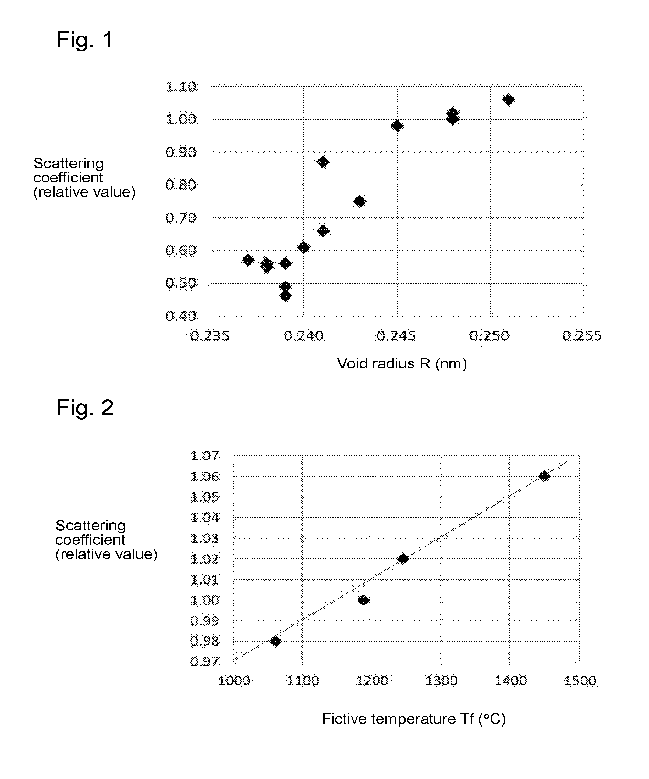
To provide low scattering silica glass suitable as a material of an optical communication fiber.Silica glass, which has a fictive temperature of at least 1,000° C., and which has a void radius of at most 0.240 nm as measured by positron annihilation lifetime spectroscopy. A method for heat-treating silica glass, which comprises holding silica glass to be heat-treated in an atmosphere at a temperature of at least 1,200° C. and at most 2,000° C. under a pressure of at least 30 MPa, and cooling the silica glass at an average temperature-decreasing rate of at least 40° C. / min during cooling within a temperature range of from 1,200° C. to 900° C. A method for heat-treating silica glass, which comprises holding silica glass to be heat-treated in an atmosphere at a temperature of at least 1,200° C. and at most 2,000° C. under a pressure of at least 140 MPa, and cooling the silica glass in an atmosphere under a pressure of at least 140 MPa during cooling within a temperature range of from 1,200° C. to 900° C.

Description

TECHNICAL FIELD[0001]The present invention relates to silica glass having a low Rayleigh scattering coefficient, and a method for heat-treating silica glass so as to reduce the Rayleigh scattering coefficient.BACKGROUND ART[0002]Transmission loss of an optical fiber has a significant impact on the performance of the optical communication network. As a material of an optical fiber, silica glass has been widely used. The transmission loss of an optical fiber in a wavelength region around 1,550 nm employed for usual optical communication network, is considered to be mainly due to Rayleigh scattering of silica glass.[0003]It is known that the higher the fictive temperature of silica glass, the higher the Rayleigh scattering coefficient of the silica glass. Thus, as a method for producing an optical fiber, a method of lowering the fictive temperature of silica glass to lower the Rayleigh scattering coefficient thereby to reduce the optical transmission loss has been proposed (Patent Docu...

Claims


Application Information

Patent Timeline
Patent Type & Authority Applications(United States)
IPC IPC(8): C03B25/02C03C3/06
CPCC03C3/06C03B25/02C03B37/02727C03B19/1453C03B32/005C03B2201/04C03B2205/56Y02P40/57C03B2201/075C03B2201/31C03B2201/42
Inventor ONO, MADOKAITO, SETSUROHONMA, OSAMUAMINO, YOUSUKE
Owner ASAHI GLASS CO LTD
Learn More