Rotating stent delivery system for side branch access and protection and method of using same

a stent and side branch technology, applied in the field of stents and stent delivery systems, can solve the problems of ineffective devices and methods for properly positioning and positioning the stent, the stent has previously been inadequately treated, and the side branch passage is not protected, so as to improve the trackability of the stent delivery system, improve the orientation of the stent, and improve the effect of the stent orientation

Inactive Publication Date: 2009-12-22
BOSTON SCI SCIMED INC
View PDF22 Cites 139 Cited by
  • Summary
  • Abstract
  • Description
  • Claims
  • Application Information

AI Technical Summary

Benefits of technology

[0017]The present invention contemplates a new and improved apparatus and method that improves the orientation of a stent by providing a more exact placement of the stent relative to the side branch passage of a bifurcation. This, in turn, leads to better protection of the side branch passage. The present invention has the potential for improvement in trackability of the stent delivery system.
[0021]In order to facilitate ease of rotation of the barrel about the axle portion of the catheter shaft a gap or space may be present between the catheter (shaft) and the barrel. In at least one embodiment the balloon defines a pair of end overlapping portions which are constructed and arranged to form a seal between the barrel and the catheter during expansion of the balloon. Such overlapping portions act to prevent or limit leakage of inflation fluid from the assembly and / or catheter through the gap(s).
[0025]In at least one embodiment a stent or other implantable device is disposed about the balloon in a reduced diameter configuration. When the balloon is expanded the stent is deployed. In the reduced state, at least a portion of the secondary guidewire housing underlies the stent to allow the secondary guidewire to effectively pass under a portion of the stent and out one of the openings in the wall of the stent. Such a configuration allows a first portion of the stent to be deployed in the primary vessel distal of the branch vessel and a second portion of the stent to be deployed proximal of the branch vessel. The stent opening through which the secondary guidewire passes maintains a side-branch opening therebetween.

Problems solved by technology

Although efforts have been made to use a stent at bifurcations, these sites have previously been inadequately treated by a stent.
However, problems are still encountered in orienting the stent relative to the side branch at the bifurcation of the main and branch passages.
These devices and methods of achieving proper angular orientation have not been shown to be effective in properly placing and positioning the stent.
As will be appreciated and understood by those skilled in the art, improper placement of the stent with respect to its rotational or circumferential orientation, or its longitudinal placement, could lead to obstruction of the side branch passage.
Commercially available devices do not maintain side branch access at the time of stent deployment.
This results in the potential for plaque shift and occlusion of the side branch passage.

Method used


Image

  • Rotating stent delivery system for side branch access and protection and method of using same
  • Rotating stent delivery system for side branch access and protection and method of using same
  • Rotating stent delivery system for side branch access and protection and method of using same

Examples


Embodiment Construction

[0041]While this invention may be embodied in many different forms, there are described in detail herein specific preferred embodiments of the invention. This description is an exemplification of the principles of the invention and is not intended to limit the invention to the particular embodiments illustrated.

[0042]For the purposes of this disclosure, like reference numerals in the figures shall refer to like features unless otherwise indicated.

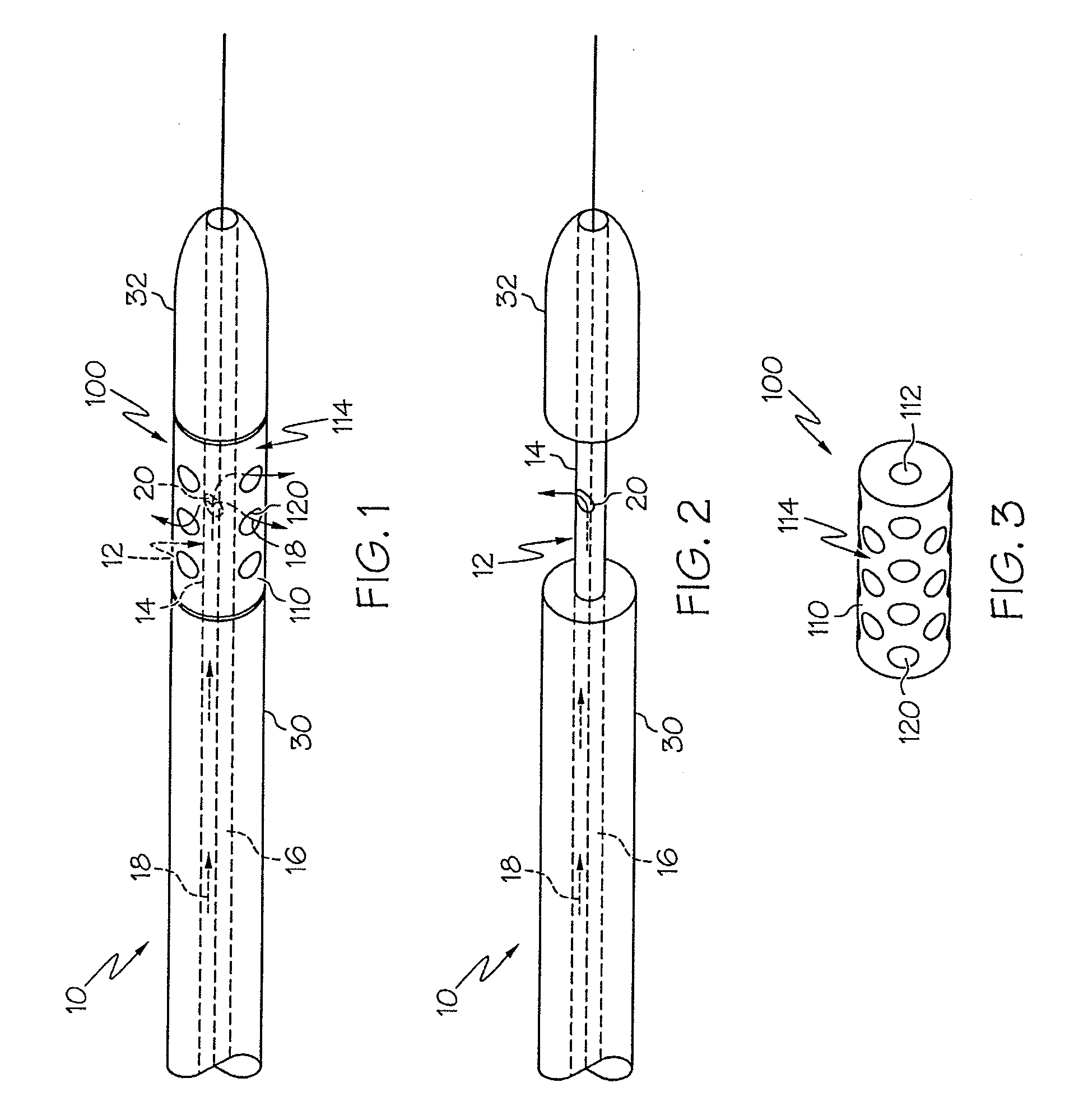
[0043]In at least one embodiment of the invention, an example which is illustrated in FIG. 1 a catheter 10 is shown having a rotational assembly 100. The rotational assembly 100, shown free of the catheter in FIG. 3, is independently rotatable about a portion of the catheter shaft 12, referred to hereinafter as an axle or axle portion 14, such as is shown in FIG. 2.

[0044]As depicted in FIG. 2 the catheter shaft 12 defines an inflation lumen 16 through which an inflation fluid, depicted as arrows 18, may be passed therethrough. A portion of ...


PUM


Abstract

A system for treatment of a vessel bifurcation and its method of use comprises a catheter having a catheter shaft, a portion of which is characterized as an axle about which a rotatable assembly is disposed and rotatable thereabout. The system employs a series of lumens, openings and / or ports to provide a balloon mounted on the rotatable assembly with fluid communication to the catheter shaft.

Description

CROSS-REFERENCE TO RELATED APPLICATIONS[0001]Not applicableSTATEMENT REGARDING FEDERALLY SPONSORED RESEARCH[0002]Not applicableBACKGROUND OF THE INVENTION[0003]1. Field of the Invention[0004]At least one embodiment of the present invention is directed to the field of stents and stent delivery systems used to treat stenoses, and more particularly to stenoses at a bifurcation of a passage and / or ostium of vessel.[0005]2. Description of the Related Art[0006]Stent systems are widely used in the treatment of stenoses. Intravascular stents are used in coronary, renal, and carotid arteries, for example, to maintain an open passage through the artery. In patients whose coronary heart disease consists of focal lesions, stents have proven effective. For example, where only a single coronary artery is clogged or where there are short blockages in more than a single artery, stents have been used with a great amount of success. An intravascular stent may be positioned in a clogged artery by a ca...

Claims


Application Information

Patent Timeline
Patent Type & Authority Patents(United States)
IPC IPC(8): A61F2/06
CPCA61F2/958A61F2/954A61F2/856A61F2002/065
Inventor GUMM, DARREL
Owner BOSTON SCI SCIMED INC
Why Eureka
Try Eureka