Planting device and planting structure for plants

a planting device and plant technology, applied in watering devices, horticulture, roof improvement, etc., can solve the problems of increasing the cost of the device or the structure, the concrete layer is also considerably heavy, and the prior art device is still in use, so as to achieve the effect of light weight, simple structure and small number of components

Inactive Publication Date: 2009-12-29
TAJIMA RYOKKA
View PDF24 Cites 13 Cited by
  • Summary
  • Abstract
  • Description
  • Claims
  • Application Information

AI Technical Summary

Benefits of technology

[0023]Further, in any planting device for plants described above, ribs may be provided on the bottom of the body portion for preventing the movement of soil and reinforcing the body portion used as a cabinet.
[0026]Further, in any planting device for plants described above, a partition plate may be provided on the bottom of the body portion for preventing the movement of soil.
[0035]The following effects can be obtained by the above constitution of the present invention.
[0036](a) Due to being simple in structure, small in number of components and light in weight, the device or the structure of the present invention can be available at a low cost and an increase in the construction efficiency.
[0037](b) Due to the fact that a scaffold is provided, various types of maintenance work can be done easily. For example, watering the plants over the surface of the soil at each of the devices is not necessary but a uniform watering can be easily done over the soil of all the devices arrayed continuously. Such watering can be done simply by allowing water to pass through a water supply pipe, thereby saving the time.
[0038](c) Where a construction surface on which greening is carried out is a gradient, the devices can be easily formed continuously to attain a high efficiency, particularly in terms of watering. In other words, in a conventional technology, spraying water must be done at each of the devices at a location having a gradient. However, in the present invention, if watering is done with the device beginning at upward step side of a gradient, the surplus water continuously flows down to the device at the downward step side of the gradient, thereby providing a proper watering all over the area of the planting device.

Problems solved by technology

However, in order to provide sufficient water retainability and water drainability for cultivating plants, a relatively large quantity of sediment must be introduced in a waterproof layer, and the concrete layer is also considerably heavy.
The combined weight of these two layers affects a building, which is a problem.
However, such a prior art device still has several problems which need to be improved.
Namely, the conventional device is complicated in structure and includes a large number of components, thereby raising costs of the device or structure and resulting in poor installation efficiency.
Further, this type of conventional device needs various kinds of maintenance work and such work is extremely difficult due to the absence of a scaffold.
For example, watering must be done over the surface of the soil of each of the devices and a uniform spraying of water all over the entire soil surface of the device is difficult particularly due to the absence of a scaffold, thereby complicating the work resulting in a longer time to complete the watering.
Also, in such a conventional device, where a construction surface on which greening is carried out is a gradient, the device cannot be formed continuously in a satisfactory manner, causing problems in watering in particular.
To be more specific, at such an installation having a gradient, watering must be done at each device, which is much more complicated and difficult due to the gradient as compared to an installation at a flat location.
However, in this technology, fixing the device to the rooftop is complicated, resulting in an increase in the installation costs and the time needed in the installation, which is a problem.
However, in the above-described planting devices, a drain plate (water retaining / supply / draining means) and a truncated cone-shaped hollow body used as the fixing means are formed integrally and made complicated in shape and larger in size as a whole.
Therefore, where resin is used to form a drain panel, it is not easy to manufacture a mold, thereby increasing costs.
Further, it is complicated and requires some work to store and transport such products.
There is, however, a difficulty in aligning the one member with the other, resulting in poor work efficiency, which is a problem.
Such necessity is not always met and this poses another problem.

Method used


Image

  • Planting device and planting structure for plants
  • Planting device and planting structure for plants
  • Planting device and planting structure for plants

Examples


Embodiment Construction

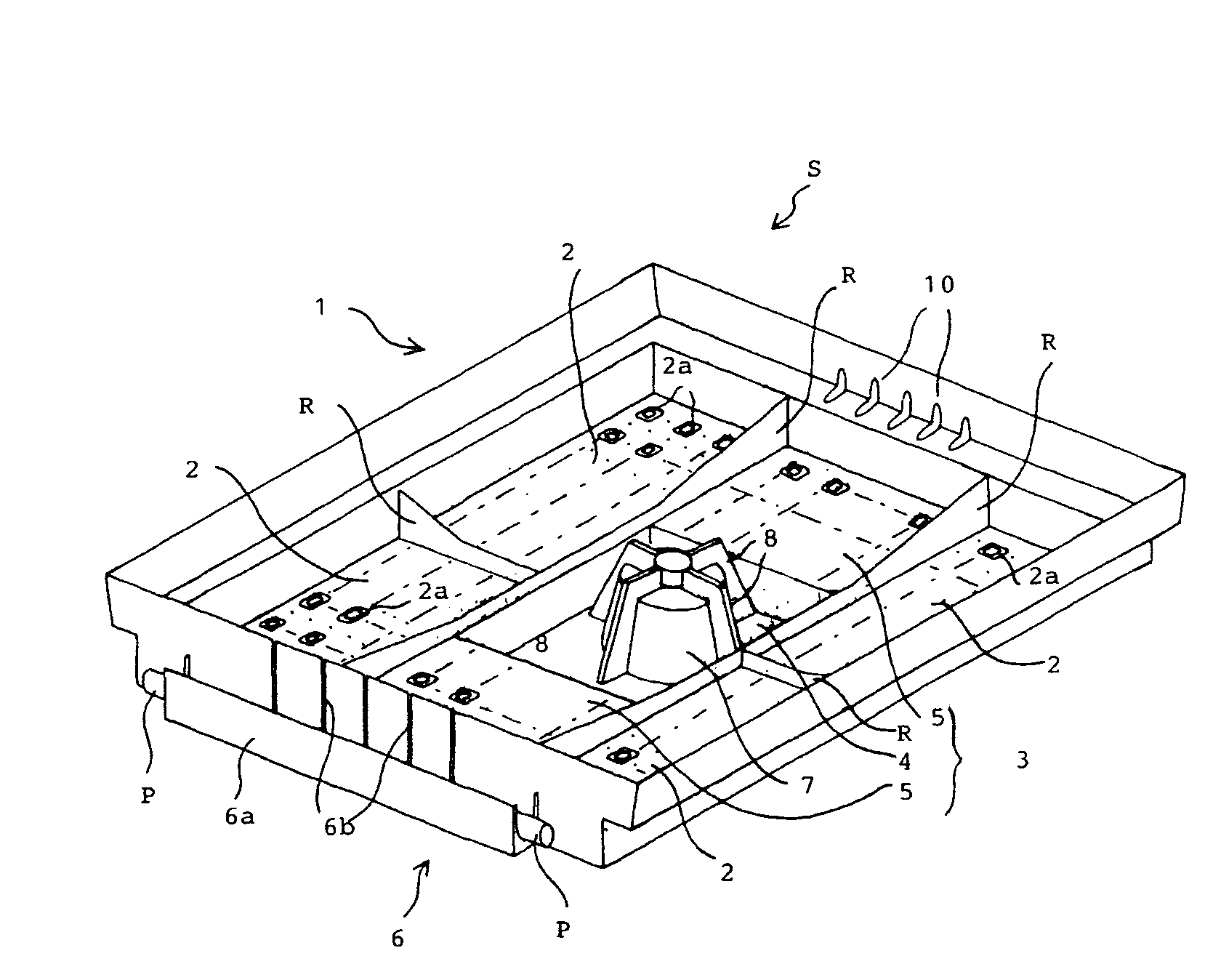
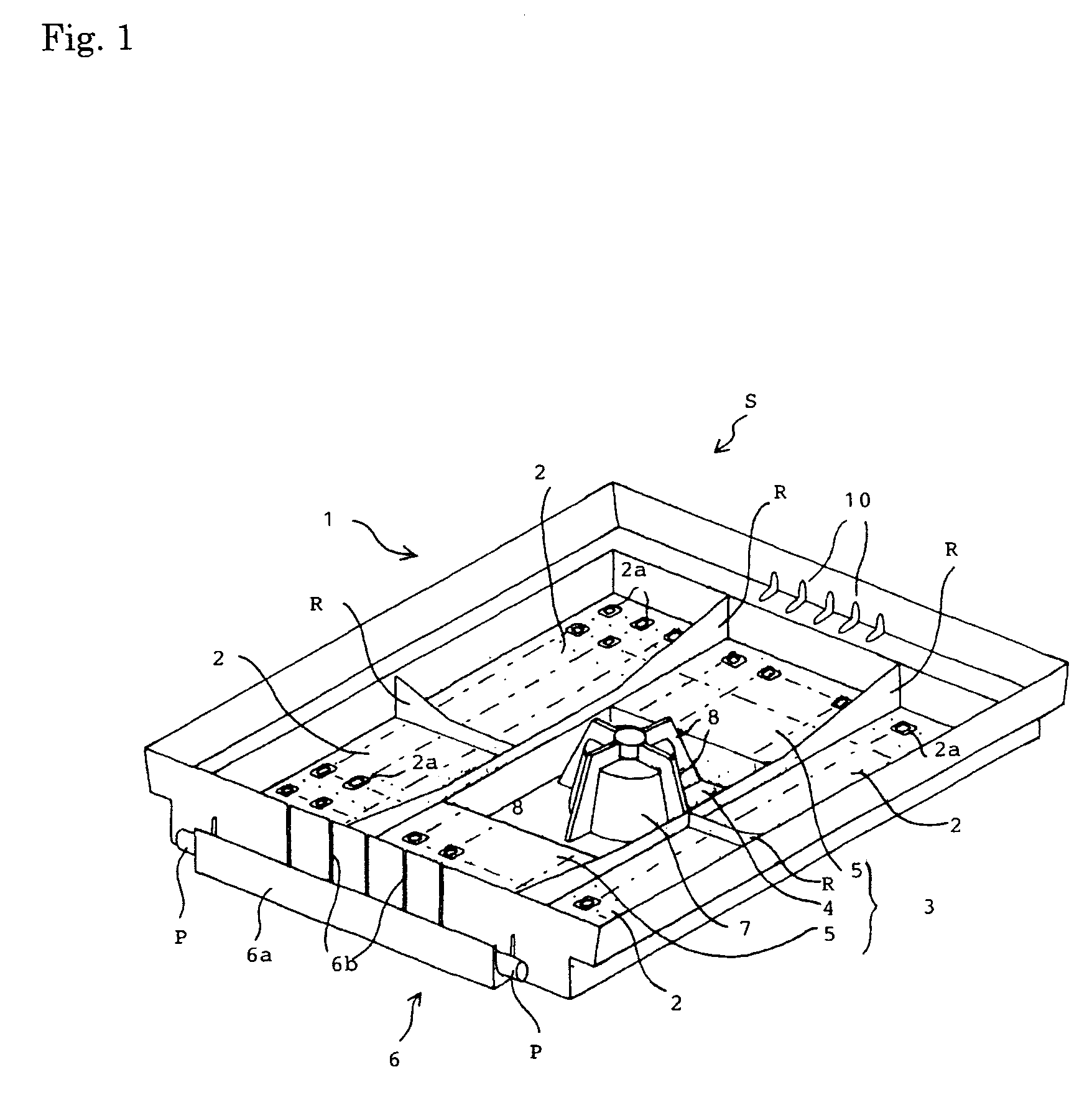
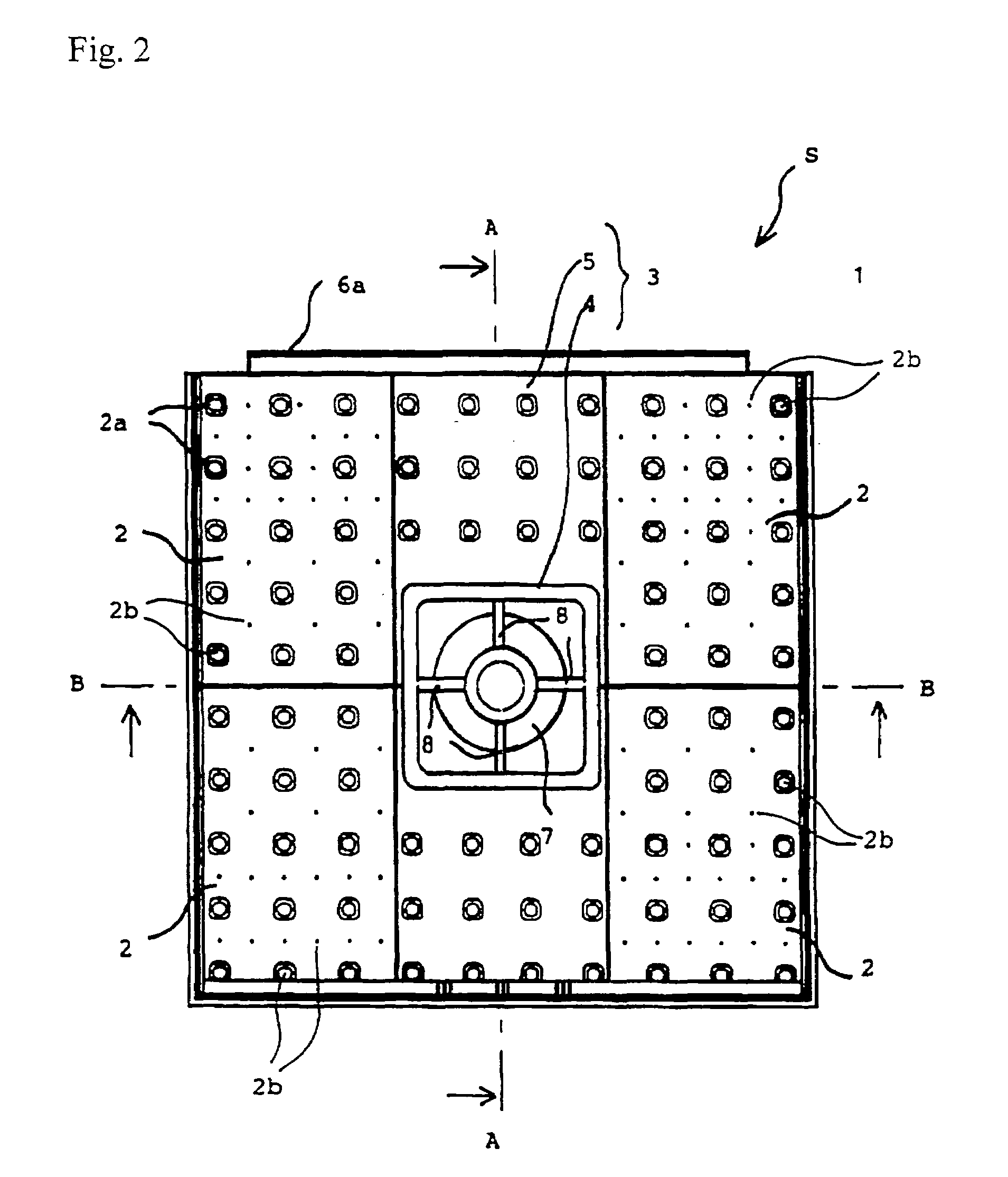
[0045]According to the present invention, a planting device is provided with a body portion having a first fixing means and a second fixing means. The first fixing means is firmly fixed to a mounting surface of the body portion. The second fixing means is linked to the first fixing means. The body portion is provided at a bottom with a water draining means, a water retaining means and the first fixing means. The body portion is also provided at a side wall with a water receiving means. Soil is filled into a surrounding space enclosed with the side walls. A water supply pipe is erected at the water receiving means, thereby supplying water to the water retaining means formed at the bottom of the body portion. Soil is filled into the body portion to plant desired plants (or a desired plant) and to cultivate the plants thereon.

[0046]The body portion comprises a rectangular plastic cabinet, and a recessed part for reinforcement of the strength of the body portion is formed at a bottom of...


PUM


Abstract

The present invention provides a planting device for plants to be formed mainly on a rooftop, a roof of a building, or the like. The planting device for plants comprises a body portion provided with a first fixing means and a second fixing means. The first fixing means is firmly fixed to a mounting surface of the body portion. The second fixing means is linked to the first fixing means. The body portion is provided at a bottom with a water draining means, a water retaining means and the first fixing means. A water receiving means is provided at a side wall of the body portion. Soil is filled into a surrounding space enclosed with the side walls and desired plants (or a desired plant) are planted on the soil. A planting structure in which multiple adjacently arranged planting devices may be used is also provided.

Description

[0001]The present application claims the benefit of Japanese patent application no. 2006-220871 filed on Aug. 14, 2006, which is incorporated herein by reference in its entirety for all purposes.BACKGROUND OF THE INVENTION[0002]1. Field of the Invention[0003]The present invention relates to a planting device for plants and a planting structure in which the device is used.[0004]The present invention relates to a device for cultivating garden trees, flowering plants and other plants easily. In particular, the present invention relates to a planting device for growing plants that is mounted on a rooftop or a roof of a building and also to a water supplying and draining board for loading soil in such a planting device.[0005]2. Description of the Related Art[0006]In recent years, a growing number of attempts have been made for planting plants on rooftops of buildings and in other spaces on a large scale to green inorganic spaces in an urban area.[0007]For this purpose, in most cases, a h...

Claims


Application Information

Patent Timeline
Patent Type & Authority Patents(United States)
IPC IPC(8): A01G9/02A01G25/00
CPCA01G9/00A01G1/007Y02B80/32Y02A30/254A01G9/033
Inventor TAJIMA, KUNIOGOTOU, YOSHIAKI
Owner TAJIMA RYOKKA
Why Eureka
Try Eureka