Cooling apparatus for a gas turbine engine igniter lead

a technology for gas turbine engines and cooling apparatuses, which is applied in the direction of burner ignition devices, power cables, cables, etc., can solve the problems of deteriorating igniter lead, engine failure to start, and failure to support required operations, and achieve the effect of facilitating cooling the igniter lead

Inactive Publication Date: 2009-12-29
GENERAL ELECTRIC CO
View PDF18 Cites 22 Cited by
  • Summary
  • Abstract
  • Description
  • Claims
  • Application Information

AI Technical Summary

Problems solved by technology

During operation, the igniter lead may be subject to an operational temperature that may cause the igniter lead to deteriorate.
As a result, the engine may fail to start and may fail to support required operations.

Method used


Image

  • Cooling apparatus for a gas turbine engine igniter lead
  • Cooling apparatus for a gas turbine engine igniter lead
  • Cooling apparatus for a gas turbine engine igniter lead

Examples


Embodiment Construction

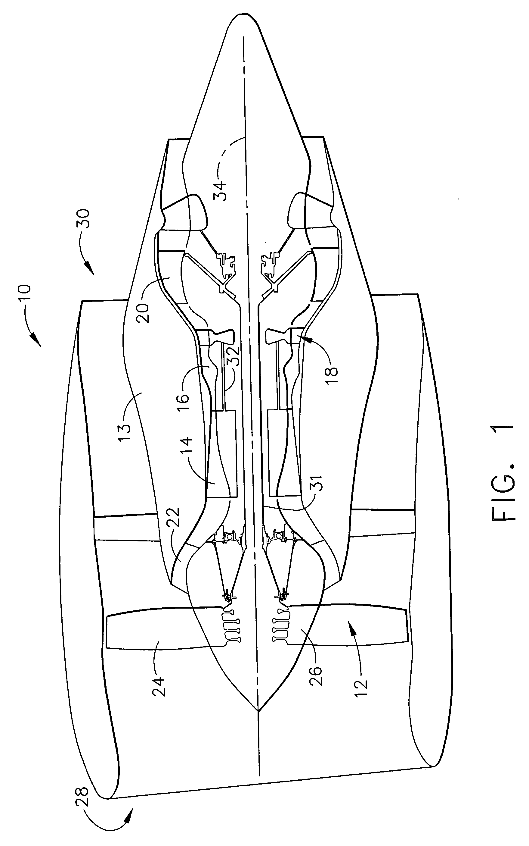
[0011]Referring to the drawings, FIG. 1 is a schematic illustration of a gas turbine engine 10 that includes a fan assembly 12 and a core engine 13 including a high pressure compressor 14, a combustor 16, and a high pressure turbine 18. Engine 10 also includes a low pressure turbine 20, and a booster 22. Fan assembly 12 includes an array of fan blades 24 extending radially outward from a rotor disc 26. Engine 10 has an intake side 28 and an exhaust side 30. In one embodiment, the gas turbine engine is a GE90 available from General Electric Company, Cincinnati, Ohio. Fan assembly 12 and turbine 20 are coupled by a first rotor shaft 31, and compressor 14 and turbine 18 are coupled by a second rotor shaft 32.

[0012]During operation, air flows through fan assembly 12, along a central axis 34, and compressed air is supplied to high pressure compressor 14. The highly compressed air is delivered to combustor 16. Airflow (not shown in FIG. 1) from combustor 16 drives turbines 18 and 20, and ...


PUM


Abstract

A method for cooling an igniter lead is provided. The method includes coupling an assembly to the igniter lead such that a portion of the assembly rotates circumferentially around the igniter lead, and channeling cooling air through the assembly to facilitate cooling the igniter lead.

Description

BACKGROUND OF THE INVENTION[0001]This invention relates generally to gas turbine engines, and more particularly, to a method and apparatus utilized to cool igniter leads used with gas turbine engines.[0002]Gas turbine engines typically include high and low pressure compressors, a combustor, and at least one turbine. The compressors compress air which is mixed with fuel and channeled to the combustor. The mixture is then ignited for generating hot combustion gases, and the combustion gases are channeled to the turbine which extracts energy from the combustion gases for powering the compressor, as well as producing useful work to propel an aircraft in flight or to power a load, such as an electrical generator.[0003]Gas turbine engines typically include an ignition system to ignite the fuel and air mixture within the gas turbine engine. At least one known gas turbine engine ignition system includes an exciter, at least one igniter, and a lead coupled between the exciter and the igniter...

Claims


Application Information

Patent Timeline
Patent Type & Authority Patents(United States)
IPC IPC(8): F02C7/264F02G1/055
CPCF02C7/266F23D2206/10Y02T50/672F23D2214/00F23D2207/00Y02T50/60
Inventor COSTELLO, HUGH MARSHALLGRONOSTAJ, RICHARD WALTER
Owner GENERAL ELECTRIC CO
Why Eureka
Try Eureka