Powered surgical tool with control module that contains a sensor for remotely monitoring the tool power generating unit

a technology of power generating unit and control module, which is applied in the direction of motor/generator/converter stopper, electronic commutator, dynamo-electric converter control, etc., can solve the problems of unprotected internal components of the tool, including the conductive components of the control circuit, corroding, and other sensitive components of the known cordless power tool that remain exposed

Active Publication Date: 2009-12-29
STRYKER CORP
View PDF17 Cites 1374 Cited by
  • Summary
  • Abstract
  • Description
  • Claims
  • Application Information

AI Technical Summary

Problems solved by technology

Powered surgical tools, unlike many other power tools, have to do more than deliver relatively large amounts of power.
Internal components of the tool, including the conductive components of its control circuit, if left unprotected in and repeatedly exposed to this environment, corrode.
However, known cordless power tools have other sensitive components that remain exposed.
These sensors are exposed to the corrosion fostering environment of the autoclave.
Nevertheless, over time, pressurized water vapor can reach these sensors.
Once this occurs, the water vapor has a tendency to corrode the sensors so as to cause their malfunction.
Even when these sensors remain shielded from the saturated water vapor, there are some disadvantages associated with their use.
Once this occurs, the variations in the signals output by the Hall sensors can cause the control circuit to generate control signals that foster tool malfunction.
Despite the best efforts of surgical personnel, it is not unheard of for surgical tools to drop to the floor.
In practice, it has proven difficult to implement this solution in a cordless powered tool.
Therefore, if a cordless powered surgical tool were driven based on the state of back EMF signals, the power required to constantly restart the motor can result in relatively rapid depletion of the battery charge.
However, a cordless power tool does not have a control console.
Thus, it has proven difficult to provide a mechanism that can be used to custom regulate the operation of the tool based on the attached accessory.
Again, since a cordless tool is not connected to this type of console, it has proven difficult to provide surgeons with this type of control with this type of tool.

Method used


Image

  • Powered surgical tool with control module that contains a sensor for remotely monitoring the tool power generating unit
  • Powered surgical tool with control module that contains a sensor for remotely monitoring the tool power generating unit
  • Powered surgical tool with control module that contains a sensor for remotely monitoring the tool power generating unit

Examples


Embodiment Construction

I. Surgical Power Tool

[0068]A. Overview

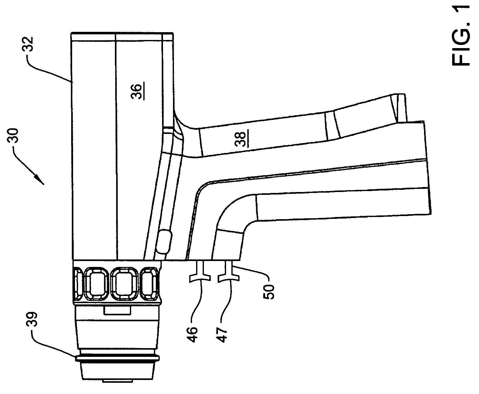
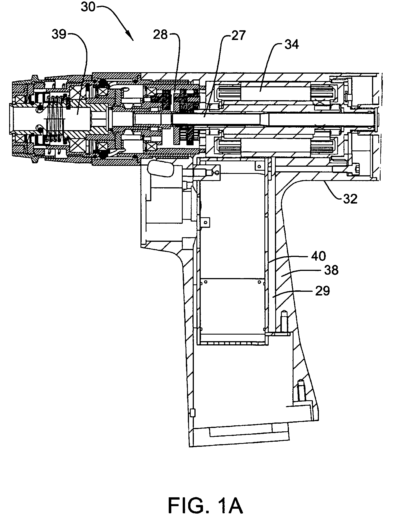
[0069]FIGS. 1 and 1A illustrate a power tool 30, a surgical tool, constructed in accordance with this invention. Tool 30 has a housing 32 in which in electrically-actuated power-generating unit is located. In the specific tool 30, this power-generating unit is a brushless, Halless, DC motor 34. Tool housing 32 is shaped to have a generally cylindrical head 36 in which motor 34 is fitted. Extending downwardly from head 36, tool housing 32 is shaped to have a handle 38.

[0070]Also contained in the head 36 is a coupling assembly 39 represented by a ring moveably mounted to the front of housing 32. Coupling assembly 39 consists of the mechanical linkage that releasably attaches a surgical attachment 41 (FIG. 16) to the motor 34 so that the motor can actuate the attachment. In some tool systems of this invention, attachment 41 is referred to as a cutting accessory. The exact structure of the coupling assembly 39 is not relevant to the structure of th...


PUM


Abstract

A powered surgical tool with a housing that contains a power generating unit such as a motor. A control module is disposed in a shell that is mounted in the housing. The control module contains a control circuit for regulating the actuation of the power generating unit. The power generating unit emits a signal representative of the operating state of the unit that is transmitted through the structural material forming the shell. Also internal to the control module shell is a sensor that monitors the signal emitted by the power generating unit. This signal output by the sensor is applied to the control circuit. The control circuit, based on the sensor signal regulates actuation of the power generating unit. Wherein the power generating unit is a motor, the signal emitted is the magnetic field that varies with rotor position. The sensor monitors the strength of this field.

Description

RELATIONSHIPS TO EARLY FILED APPLICATIONS[0001]This application claims priority under 35 U.S.C Sec. 119 from U.S. Provisional Patent Application No. 60 / 694,592 filed 28 Jun. 2005 and U.S. Provisional Patent Application No. 60 / 809,645 filed 31 May 2006.FIELD OF THE INVENTION[0002]This invention is generally related to electrically powered surgical tools. More particularly, this invention is related to a cordless, powered surgical tool with a sealed module in which the circuit that controls the activation of the tool is enclosed.BACKGROUND OF THE INVENTION[0003]In modern surgery, one of the most important instruments available to medical personnel is the powered surgical tool. Often this tool is in the form of a drill unit in which a motor is housed. Secured to the drill unit is a cutting attachment designed for application to a surgical site on to perform a specific medical procedure. For example, some powered surgical tools are provided with drills, burs or reamers for cutting bores...

Claims


Application Information

Patent Timeline
Patent Type & Authority Patents(United States)
IPC IPC(8): H02P1/00
CPCA61B17/151H02P7/06A61B17/1626B01F11/0054B01F13/0022B01F13/0028B01F15/00253B01F15/00318B01F15/00389B01F15/00409B01F15/06H02P6/16A61B17/1697A61B17/32002A61B19/5244A61B2017/00017A61B2017/00367A61B2017/00734A61B2019/5248A61B2019/5251A61B2019/5255B01F2015/00636A61B17/1622A61B2034/2048A61B2034/2055A61B34/20A61B2034/2051B01F31/40B01F33/50115B01F33/50111B01F35/2207B01F35/22161B01F35/221422B01F35/2209B01F35/332B01F35/90H02K11/215H02K11/33H02K7/145A61B17/15
Inventor PHILIPP, CHRISTOPHERMALACKOWSKI, DON
Owner STRYKER CORP
Why Eureka
Try Eureka