
Access control system with energy-saving optical token presence sensor system

a technology of optical tokens and access control systems, applied in the field of access control systems, can solve the problems of large investment of time and expense in purchasing and installing wires, prone to reliability and security failures of wire-based systems, incurring additional time and expense, etc., and achieves the effect of minimizing energy consumption, minimizing battery life, and minimum elapsed tim

Active Publication Date: 2009-12-29
HARROW PRODS
View PDF49 Cites 11 Cited by
  • Summary
  • Abstract
  • Description
  • Claims
  • Application Information

AI Technical Summary

Benefits of technology

Significantly reduces power consumption and extends battery life, enhancing the operational efficiency and cost-effectiveness of wireless access control systems by activating the token reader only when a token is presented, while maintaining robust communication and security.

Problems solved by technology

The use of wired connections between the access control module and the locking module necessitates a large investment of time and expense in purchasing and installing the wires.
Additionally, wire-based systems are prone to reliability and security failures.
If a wire connection is cut or goes, the only alternative is to repair the faulty location (which may not be feasible) or run new wire all the way from the access control module to the locking module, thus incurring additional time and expense.
Such a wireless access system is typically less expensive to install and maintain due to the minimization of wire and the necessary installation time.
However, one difficulty often encountered in installing and maintaining such a wireless access system is providing power to the individual, remote locking modules.
For example, many functions of the locking module may be quite demanding of power.
However, maintenance costs associated with frequently changing the power sources for each of the locking modules would be highly undesirable.

Method used


Image

  • Access control system with energy-saving optical token presence sensor system
  • Access control system with energy-saving optical token presence sensor system
  • Access control system with energy-saving optical token presence sensor system

Examples


Embodiment Construction

[0014]The present application may be employed in a wireless access system. Additional disclosure of such a wireless access system may be found in the following applications which are hereby incorporated by reference in their entirety: application Ser. No. 10 / 261,933, entitled “RF Channel Linking Method and System” filed Sep. 30, 2002; application Ser. No. 10 / 262,207, entitled “Energy Saving Motor-Driven Locking Subsystem” filed Sep. 30, 2002; application Ser. No. 10 / 262,509, entitled “Cardholder Interface for an Access Control System” filed Sep. 30, 2002; application Ser. No. 10 / 262,196, entitled “System Management Interface for Radio Frequency Access Control” filed Sep. 30, 2002; application Ser. No. 10 / 262,194, entitled “Power Management for Locking System” filed Sep. 30, 2002; application Ser. No. 10 / 262,507, entitled “General Access Control Features for a RF Access Control System” filed Sep. 30, 2002; application Ser. No. 10 / 262,077, entitled “RF Wireless Access Control for Lock...


PUM


Abstract

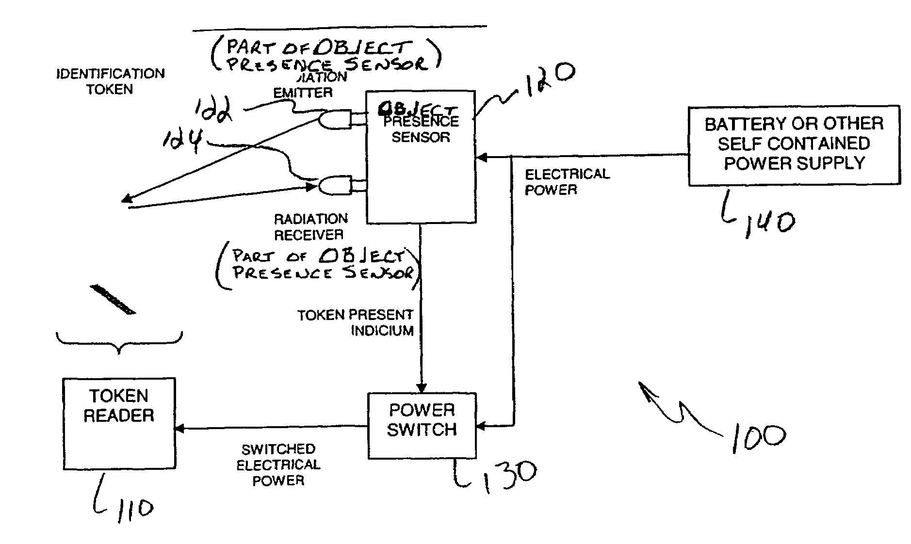
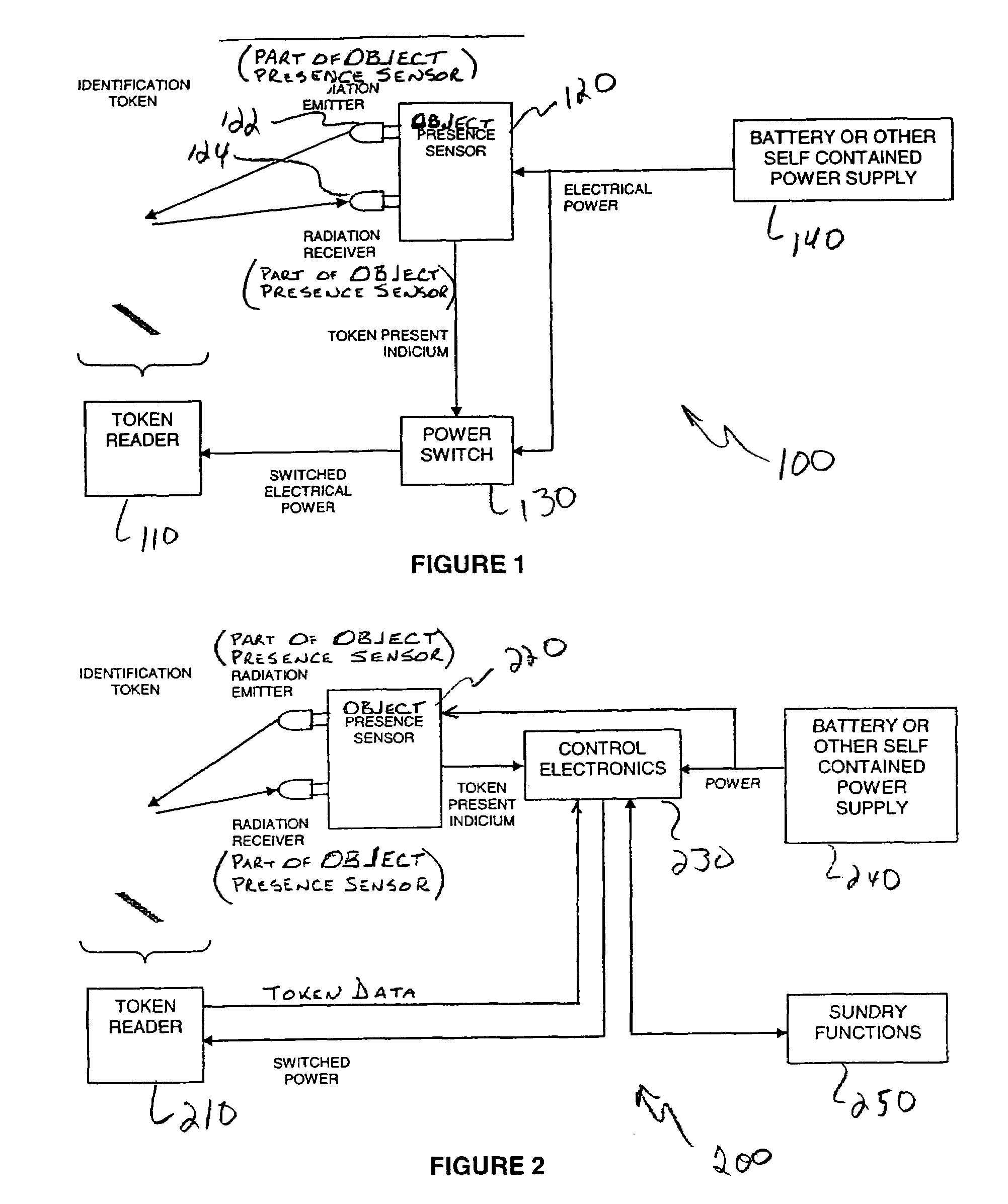
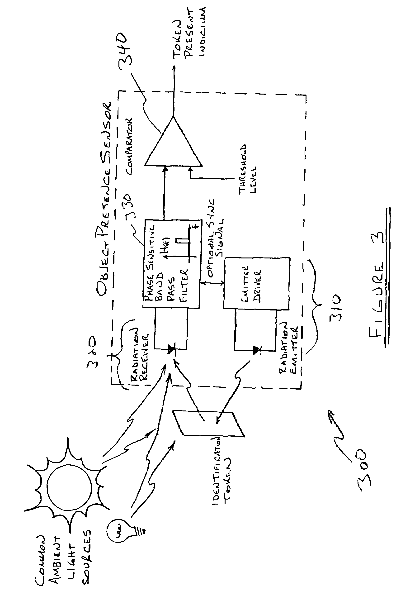
An access control system having an energy-saving optical presence sensor system is provided. The access control system includes a relatively lower operating power object presence sensor system for optically sensing the presence of a token as well in addition to a relatively higher operating power token reader for reading the token. The token reader remains unpowered until a token is detected by the object presence sensor system, which is preferably always powered. Once an object is detected by the object presence sensor system, power is supplied to the token reader and the token is read. After the token has been read, power ceases to be applied to the token reader, although the object presence sensor remains powered.

Description

RELATED APPLICATIONS[0001]The present application claims priority to the following applications: application Ser. No. 10 / 261,933, entitled “RF Channel Linking Method and System” filed Sep. 30, 2002; application Ser. No. 10 / 262,207, entitled “Energy Saving Motor-Driven Locking Subsystem” filed Sep. 30, 2002; application Ser. No. 10 / 262,509, entitled “Cardholder Interface for an Access Control System” filed Sep. 30, 2002; application Ser. No. 10 / 262,196, entitled “System Management Interface for Radio Frequency Access Control” filed Sep. 30, 2002; application Ser. No. 10 / 262,194 entitled “Power Management for Locking System” filed Sep. 30, 2002; application Ser. No. 10 / 262,507, entitled “General Access Control Features for a RF Access Control System” filed Sep. 30, 2002; application Ser. No. 10 / 262,077, entitled “RF Wireless Access Control for Locking System” filed Sep. 30, 2002; application Ser. No. 10 / 262,508, entitled “Maintenance / Trouble Signals for a RF Wireless Locking System” f...

Claims


Application Information

Patent Timeline
Patent Type & Authority Patents(United States)
IPC IPC(8): G06F7/04G05B19/00G06F7/00G07C9/00H04B1/00H04B1/38H04B3/00H04Q1/00H04Q9/00
CPCG07C9/00309G07C2009/00373G07C2209/65G07C2209/64G07C2009/00642
Inventor WIEMEYER, JAMES F.
Owner HARROW PRODS
Learn More