

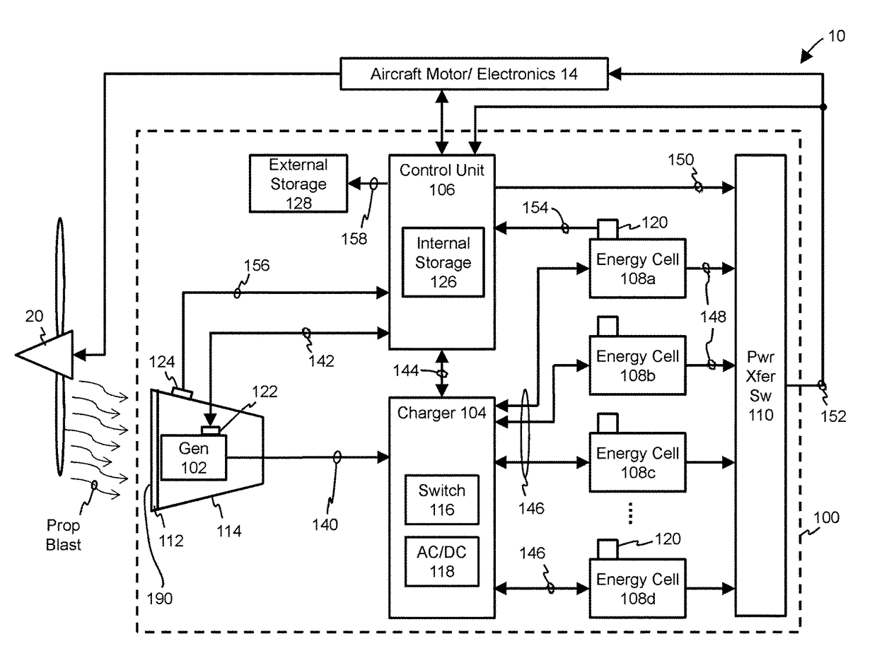
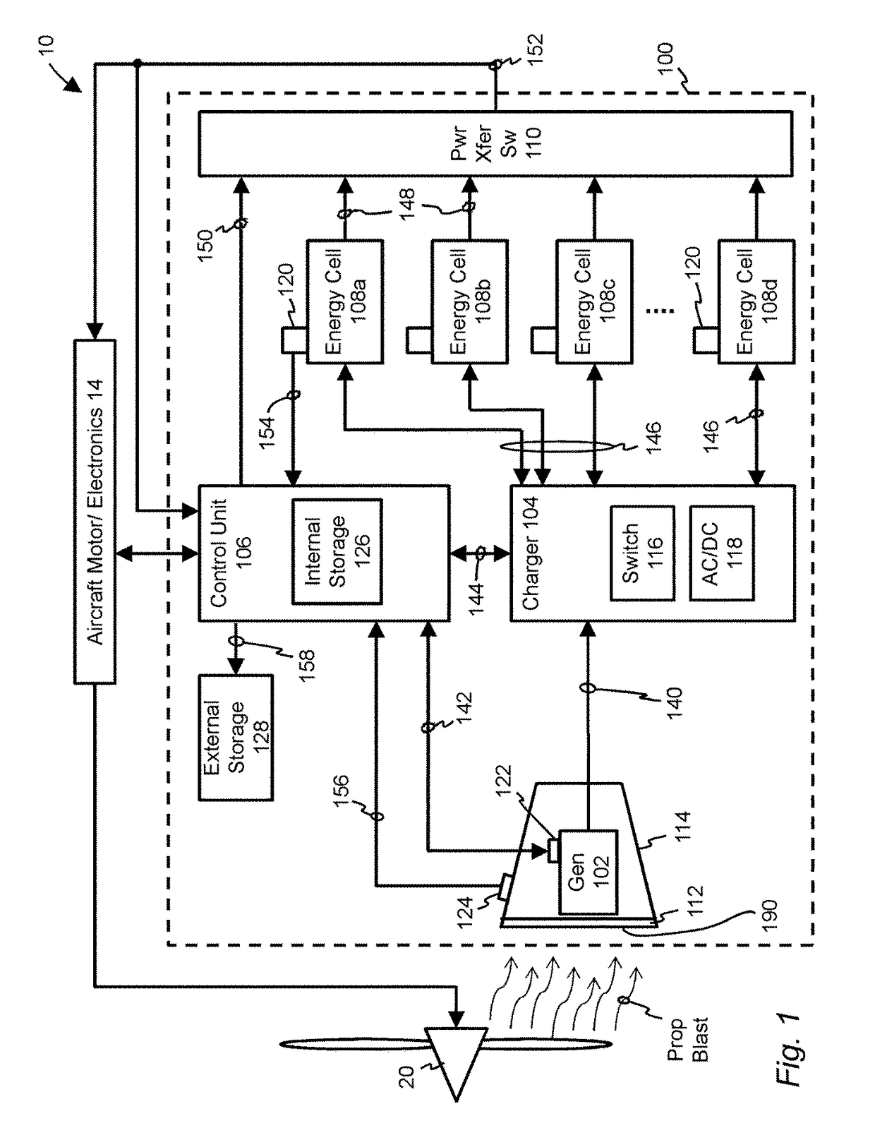
Energy cell regenerative system for electrically powered aircraft
a regenerative system and energy cell technology, applied in the direction of energy-efficient board measures, efficient propulsion technologies, electric motor propulsion transmission, etc., can solve the problems of requiring substantial downtime, most all-electric cars take a long time to recharge their on-board batteries, and electric vehicles concern their range, etc., to achieve more efficient energy conversion, stable electrical output, and high airflow
- Summary
- Abstract
- Description
- Claims
- Application Information
AI Technical Summary
Benefits of technology
Problems solved by technology
Method used
Image

Examples
Embodiment Construction
[0050]The present teachings are described more fully hereinafter with reference to the accompanying drawings, in which the present embodiments are shown. The following description is presented for illustrative purposes only and the present teachings should not be limited to these embodiments. Any system or controller configuration and architecture satisfying the requirements described herein may be suitable for implementing the energy cell regenerative system and method of the present embodiments.
[0051]As used herein, the terms “energy cell”, in both singular and plural form, encompasses energy packs, power cells, electrochemical cells, batteries, capacitors, supercapacitors, ultracapacitors and the like.
[0052]As used herein, the term “aircraft” encompasses propeller-driven aircraft, including propeller airplanes, light sport and ultra-light vehicles and motor gliders, unmanned aerial vehicles and unmanned aerial systems (drones), helicopters, blimps, pusher propeller airplanes, and...
PUM
 Abstract
Description
Claims
Application Information