Power saving control system for negative pressure wound therapy pumps

a control system and negative pressure technology, applied in the direction of suction devices, intravenous devices, other medical devices, etc., can solve the problems of difficult maintenance of multi-component apparatuses powered by disposable batteries with limited stored energy, and achieve the effects of simple and effective use, carefree maintenance, and durable construction

Active Publication Date: 2014-10-14
MEDU SCI
View PDF12 Cites 31 Cited by
  • Summary
  • Abstract
  • Description
  • Claims
  • Application Information

AI Technical Summary

Benefits of technology

[0013]It is an advantage of this invention that the battery powered pump will be operable for a maximum length of time without requiring a change of batteries.
[0021]It is yet another advantage of this invention that the power consumption of the pump is minimized while providing an effective operation of the pump.
[0023]It is a further advantage of this invention that the modulation circuit provides an intermittent operation of the pump as required by the microprocessor for the operation of the medical device associated with the pump.
[0024]It is yet another object of this invention to provide a medical device pump with an operating system which is durable in construction, carefree of maintenance, and simple and effective in use.
[0025]These and other objects, features and advantages are accomplished according to the instant invention by providing an operating system for a medical device pump in which the microprocessor controls the operation of the pump features in a manner to minimize power consumption and maximize the life of the batteries powering the operation of the pump. The microprocessor associated with the medical device pump includes a modulation circuit that operates the pump on an intermittent basis and only when a pressure sensor indicates that the pressure asserted by the pump is at a threshold level. The operation of other sensors are powered only in situations when information from the sensor is needed, while other more essential sensors are operated on an intermittent basis by the modulation circuit. A fill sensor is operated intermittently, while a tilt sensor is only activated when a signal is received from the fill sensor. An optical sensor is only activated when the canister is removed from the pump housing, while the pump is de-powered whenever the optical sensor is activated.

Problems solved by technology

Powering a multi-component apparatus from disposable batteries having limited stored energy is difficult to maintain.

Method used


Image

  • Power saving control system for negative pressure wound therapy pumps
  • Power saving control system for negative pressure wound therapy pumps
  • Power saving control system for negative pressure wound therapy pumps

Examples


Embodiment Construction

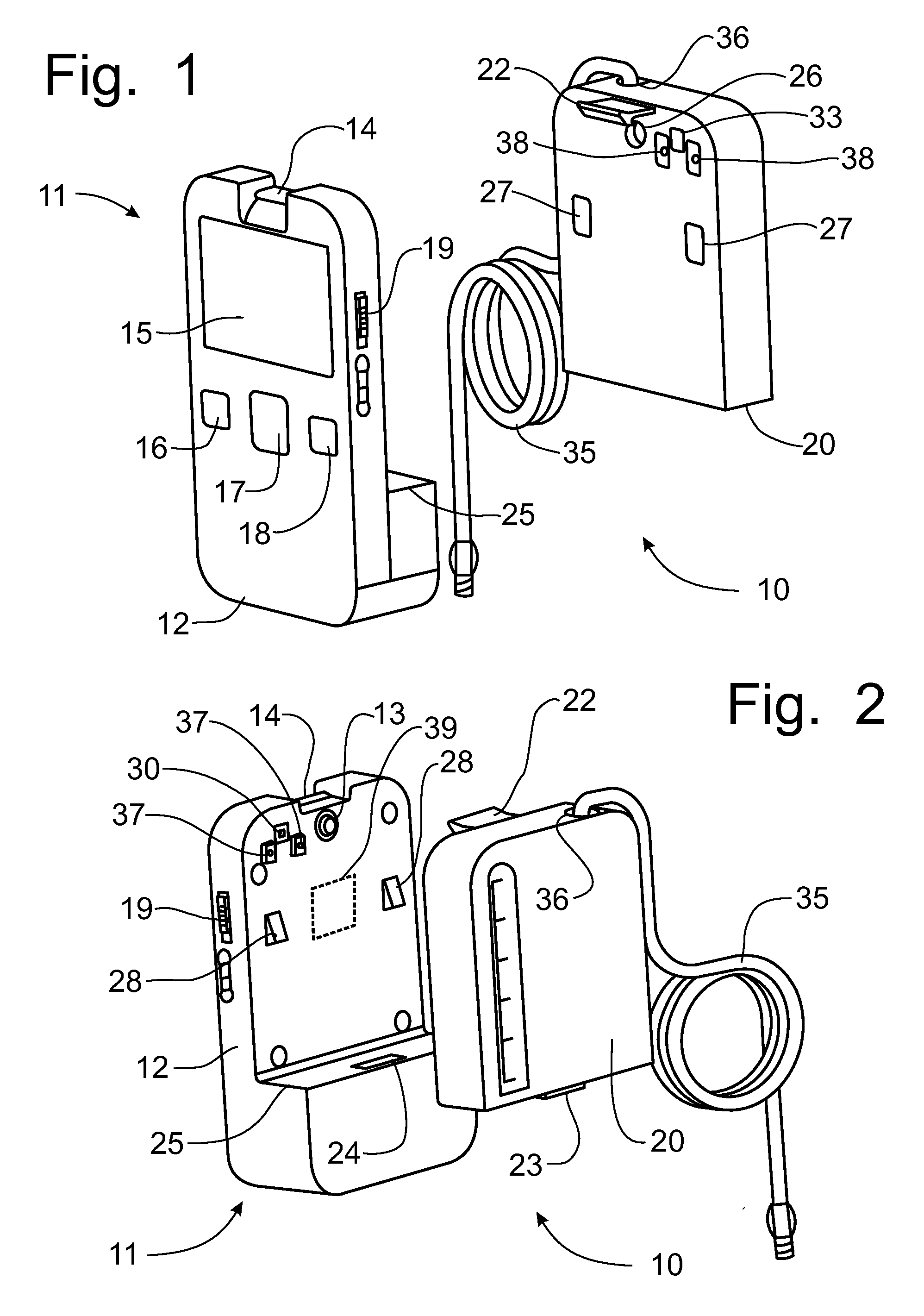
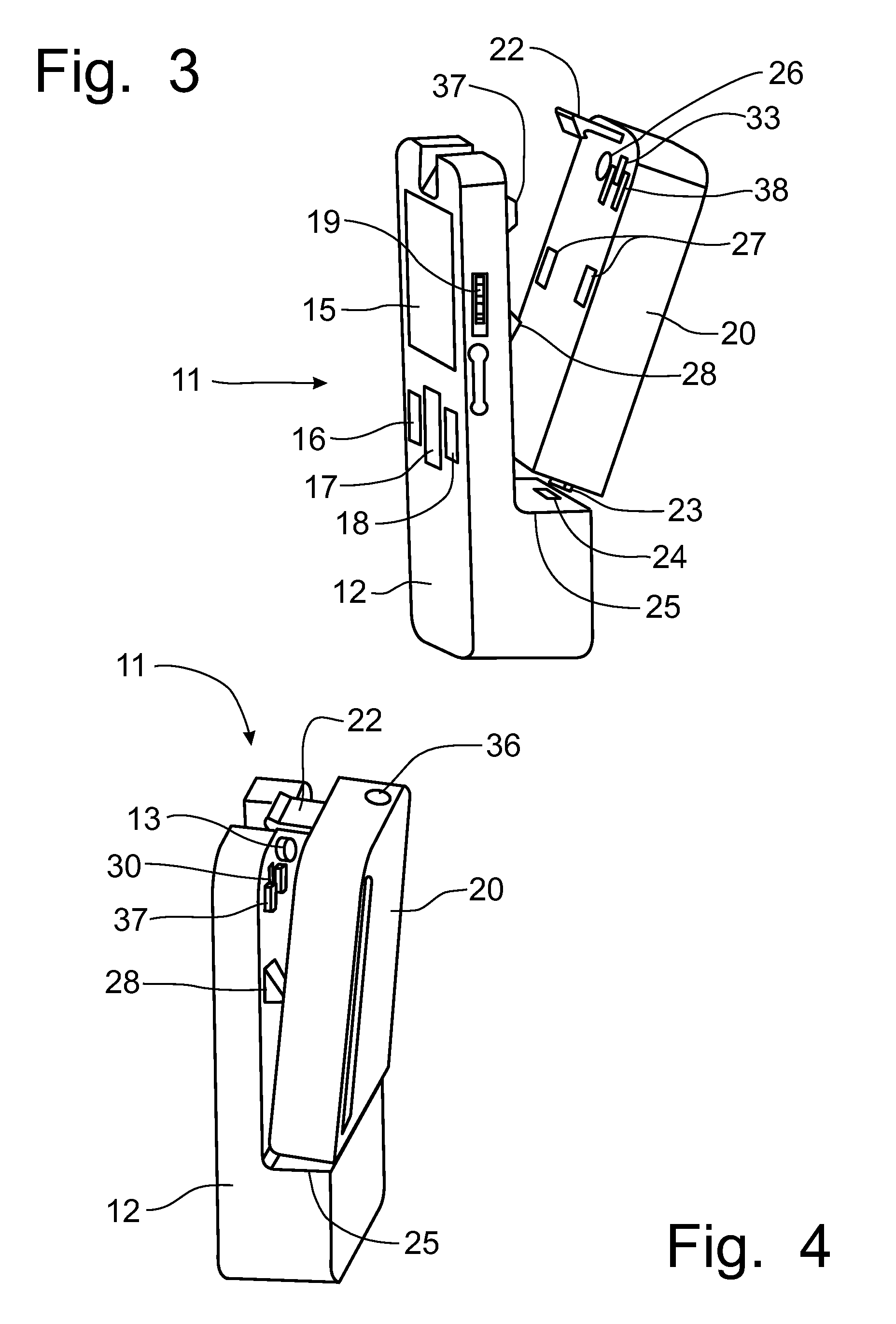
[0034]Referring to FIGS. 1-5, a pump for a negative pressure wound therapy system 10 can best be seen. The system 10 includes a pump 11 mounted in a pump housing 12 that draws a vacuum from the vacuum port 13 for the purposes of extracting fluids and exudates from a negative pressure bandage 34, as will be discussed in greater detail below. The pump housing 12 is provided with a display screen 15 and control buttons 16-19 for operating of the pump 11 and monitoring the function thereof. The top surface of the pump housing 12 is formed with a latch keeper 14 to retain the canister 20 on the pump housing in operative communication therewith, as will also be described in greater detail below. In the way of examples, the control buttons 16-19 can provide operations control for the pump 10. The control button 16 can be used to set the operating pressure for the pump 10. Control button 17 can be used to turn the pump 10 on and off to start or stop the negative pressure therapy. Control bu...


PUM


Abstract

An operating system for a medical device pump has a microprocessor controlling the operation of the pump features in a manner to minimize power consumption and maximize the life of the batteries powering the pump. The microprocessor associated with the medical device pump includes a modulation circuit that operates the pump on an intermittent basis and only when a pressure sensor indicates that the pressure asserted by the pump is at a threshold level. The operation of other sensors are powered only in situations when information from the sensor is needed, while other more essential sensors are operated on an intermittent basis by the modulation circuit. A fill sensor is operated intermittently, while a tilt sensor is only activated when a signal is received from the fill sensor. An optical sensor is only activated when the canister is removed from the pump housing, during which the pump is de-powered.

Description

CROSS-REFERENCE TO RELATED APPLICATIONS[0001]This application claims domestic priority on U.S. Provisional Patent Application Ser. No. 61 / 620,608, filed on Apr. 5, 2012, the content of which is incorporated herein by reference.FIELD OF THE INVENTION[0002]The present invention relates generally to negative pressure wound therapy system and, more particularly, to a control system that will control energy consumption from the battery powering the operation of the negative pressure pump.BACKGROUND OF THE INVENTION[0003]Negative pressure wound therapy involves a bandage system that is applied to the wound site on the patient to create a seal around the perimeter of the bandage system and around a periphery of the wound to be treated. The negative pressure bandage system is provided with a connector that connects to a pump that draws a vacuum on the bandage system to urge any fluid and exudates within the wound site to move toward the pump through a conduit interconnecting the connector a...

Claims


Application Information

Patent Timeline
Patent Type & Authority Patents(United States)
IPC IPC(8): A61M1/00
CPCA61M1/0088A61M1/0037A61M2205/18A61M2205/215A61M2205/50A61M2205/8206A61M2205/8212A61M2205/3382A61M1/75A61M1/982A61M1/96
Inventor PAN, LILI, JIANGLIN, HUIYONG
Owner MEDU SCI
Why Eureka
Try Eureka