Supercharge Your Innovation With Domain-Expert AI Agents!

Fluid control valve

a control valve and flue gas technology, applied in the direction of diaphragm valves, valve details, valve arrangements, etc., can solve the problems of inability to achieve stable performance and insufficient respons

Inactive Publication Date: 2010-01-05
FUJIKURA COMPOSITES INC
View PDF7 Cites 5 Cited by
  • Summary
  • Abstract
  • Description
  • Claims
  • Application Information

AI Technical Summary

Benefits of technology

The design enables a quick-response fluid control valve with stable performance, preventing the occurrence of shock waves and ensuring smooth pressure regulation, allowing for precise control of air flow and pressure in control port chambers.

Problems solved by technology

Although a quick response is required in this type of conventional fluid supply valve, the response thereof is not always sufficiently quick enough.
Additionally, although it is absolutely necessary to increase the velocity of flow of air to improve the response of the fluid supply valve, there has been a problem with a stable performance not being achievable due to uncertain vortexes, shock waves, boundary-layer separation point variations, stagnation, etc., occurring if the velocity of flow of air is increased.

Method used


Image

  • Fluid control valve
  • Fluid control valve
  • Fluid control valve

Examples


Embodiment Construction

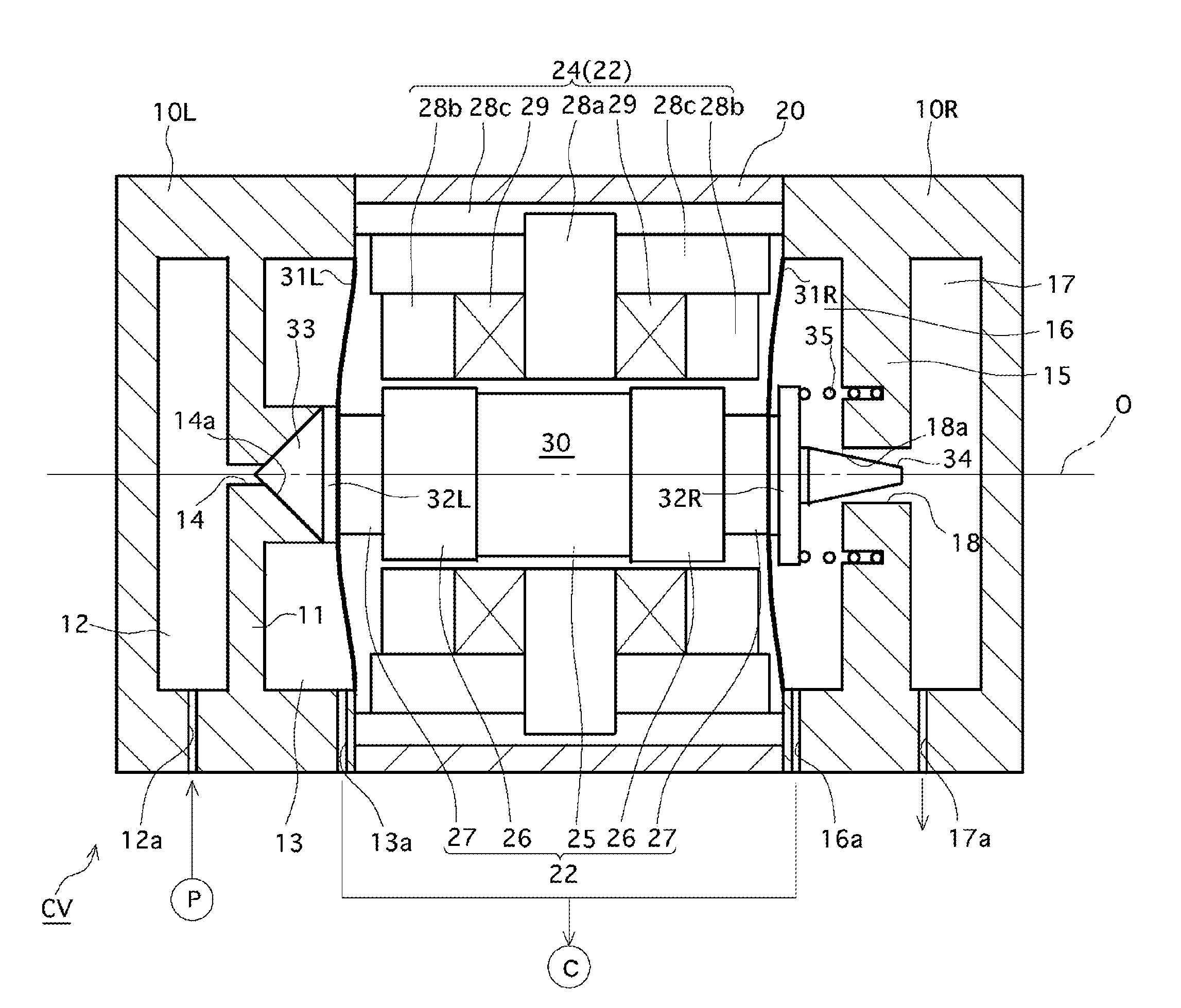
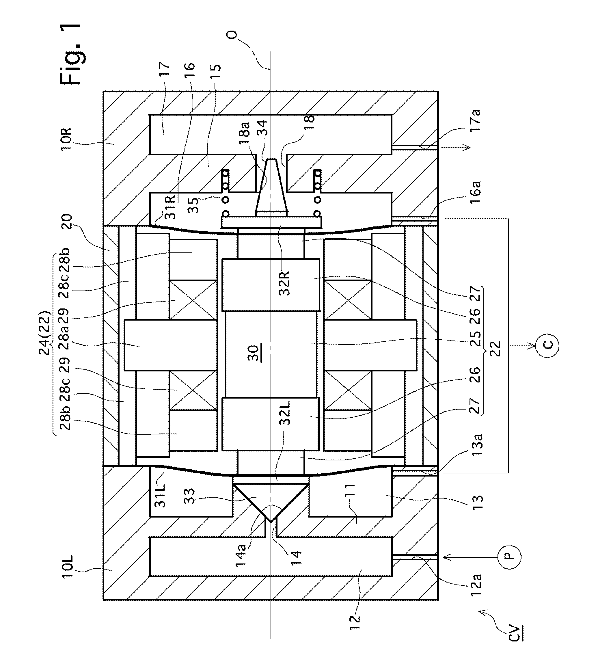
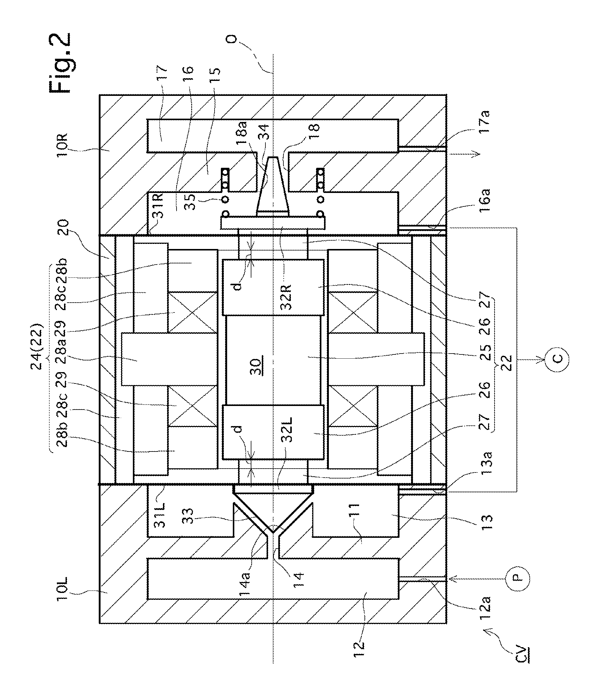
[0021]FIGS. 1 and 2 show a first embodiment of a fluid control valve CV according to the present invention. The fluid control valve CV has a generally columnar shape which is rotationally symmetrical about an axis O. The fluid control valve CV is provided with a left fluid channel block 10L and a right fluid channel block 10R, and is further provided, at a center of the fluid control valve CV between the left fluid channel block 10L and the right fluid channel block 10R, with a control block 20. The fluid control valve CV is provided in the left fluid channel block 10L with an air supply port chamber 12 and a control port chamber 13 which are isolated from each other by a partition 11 formed therebetween. The fluid control valve CV is provided, in the left fluid channel block 10L on the axis O, with an air supply nozzle 14 which is formed through the partition 11 so that the air supply port chamber 12 and the control port chamber 13 are communicatively connected to each other throug...


PUM


Abstract

An object of the present invention is to obtain a quick-response fluid control valve.A fluid control valve includes a pressure chamber including an output port; an air supply nozzle and an air exhaust nozzle which are communicatively connected to the pressure chamber and positioned on a common straight line; a flapper assembly which is movable between the air supply nozzle and the air exhaust nozzle and includes a pair of opening / closing control surfaces that face an opening end of the air supply nozzle and an opening end of the air exhaust nozzle, respectively; and a flapper-assembly moving mechanism which moves the flapper assembly so that a distance between the opening end of the air supply nozzle and one of the pair of opening / closing control surfaces increases while a distance between the opening end of the air exhaust nozzle and the other of the pair of opening / closing control surfaces decreases.

Description

CROSS REFERENCE TO RELATED APPLICATION[0001]This application claims the benefit of PCT Application No. PCT / JP2006 / 300473, filed Jan. 17, 2006 and Japanese Patent Application No. 2005-26587, filed Feb. 2, 2005, the disclosures of which are herein incorporated by reference in their entirety.FIELD OF THE INVENTION[0002]The present invention relates to a fluid control valve which selectively exerts pressure of an air supply port on control ports.BACKGROUND OF THE INVENTION[0003]A fluid supply valve used for exerting pressure on a pressure-controlled device as constant as possible, is known in the art.[0004]Although a quick response is required in this type of conventional fluid supply valve, the response thereof is not always sufficiently quick enough. Additionally, although it is absolutely necessary to increase the velocity of flow of air to improve the response of the fluid supply valve, there has been a problem with a stable performance not being achievable due to uncertain vortexes...

Claims


Application Information

Patent Timeline
Patent Type & Authority Patents(United States)
IPC IPC(8): F16K31/08
CPCF16K11/044F16K31/082F16K31/0693F16K31/0679F16K7/17F16K31/126F16K31/42
Inventor CHINDA, HIROSHI
Owner FUJIKURA COMPOSITES INC
Features
  • R&D
  • Intellectual Property
  • Life Sciences
  • Materials
  • Tech Scout
  • Unparalleled Data Quality
  • Higher Quality Content
  • 60% Fewer Hallucinations
Learn More