Fuel cell

a fuel cell and fuel cell technology, applied in the field of fuel cells, can solve the problems of disadvantageous heat exchange efficiency, insufficient electromotive force to be used as a power source of a battery car, and structurally difficult to increase the output density per unit area of the fuel cell in the plane form, so as to improve heat exchange efficiency and power generation performance, and improve gas diffusivity

Inactive Publication Date: 2010-01-05
TOYOTA JIDOSHA KK
View PDF6 Cites 4 Cited by
  • Summary
  • Abstract
  • Description
  • Claims
  • Application Information

AI Technical Summary

Benefits of technology

[0019]According to the aspect of the present invention, since the internal charge collector is hollow, it is possible to make heat exchange with each tubular fuel cell including the hollow electrolyte membrane and the electrodes at quite a close position to the tubular fuel cell by circulating the heat medium. Therefore, the present invention can provide the fuel cell capable of improving the heat exchange efficiency with respect to the tubular fuel cells.
[0020]According to the aspect of the present invention, the reaction gas channel is formed on the outer peripheral surface of the internal charge collector, thereby making it possible to ensure diffusivity of gas into the electrode arranged inside of the electrolyte membrane. By so configuring, therefore, it is possible to provide the fuel cell capable of improving the power generation performance by improved gas diffusivity in addition to the above-stated advantages.
[0021]Furthermore, according to the aspect of the present invention, the condition is set to 0.02≦X / (X+Y)≦0.5. It is thereby possible to provide the fuel cell capable of ensuring gas diffusion efficiency while improving the cooling efficiency of the tubular fuel cells.
[0022]Moreover, according to the aspect of the present invention, the coolant is circulated in the hollow portion of the internal charge collector, thereby making it possible to cool each tubular fuel cell at quite a close position to the tubular fuel cell. By so configuring, therefore, it is possible to provide the fuel cell capable of improving the cooling efficiency of the tubular fuel cells.
[0023]Further, according to the aspect of the present invention, the member having good heat conductivity is provided in the thick portion of the internal charge collector, thereby making it possible to improve the heat conductivity of the internal charge collector. By so configuring, therefore, it is possible to provide the fuel cell capable of further improving the heat exchange efficiency with respect to the tubular fuel cells.

Problems solved by technology

Meanwhile, a unit cell of the PEFC includes constituent elements such as an electrolyte membrane, a cathode and an anode each including at least a catalyst layer, and separators, and has a theoretical electromotive force of 1.23 V. However, such a theoretical electromotive force is insufficiently low to use as a power source of a battery car or the like.
For these reasons, it is structurally difficult to increase the output density per unit area in the fuel cell in the plane form.
Because of a long distance between the coolant and a heat generator, heat exchange (cooling) efficiency disadvantageously tends to deteriorate.
With the latter technique, heat exchange (cooling) efficiency disadvantageously tends to deteriorate.

Method used


Image

  • Fuel cell
  • Fuel cell
  • Fuel cell

Examples


first embodiment

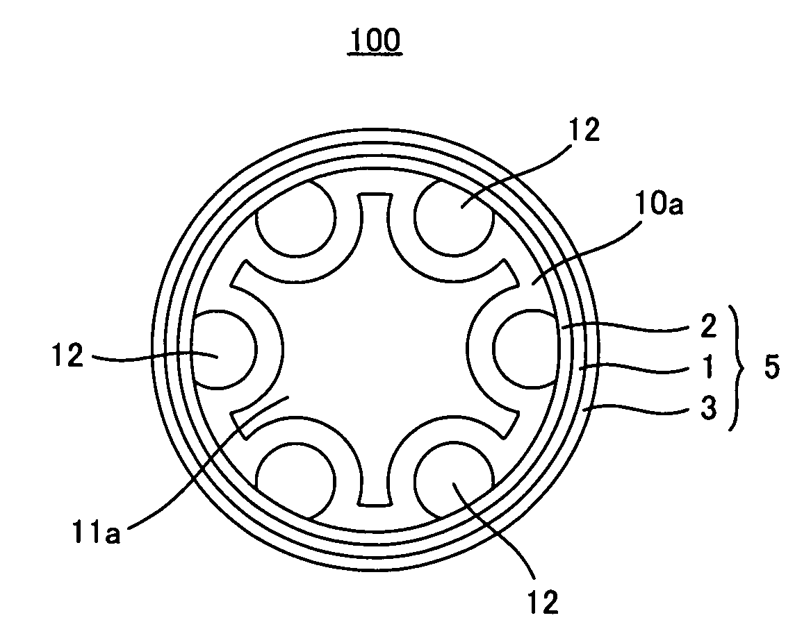
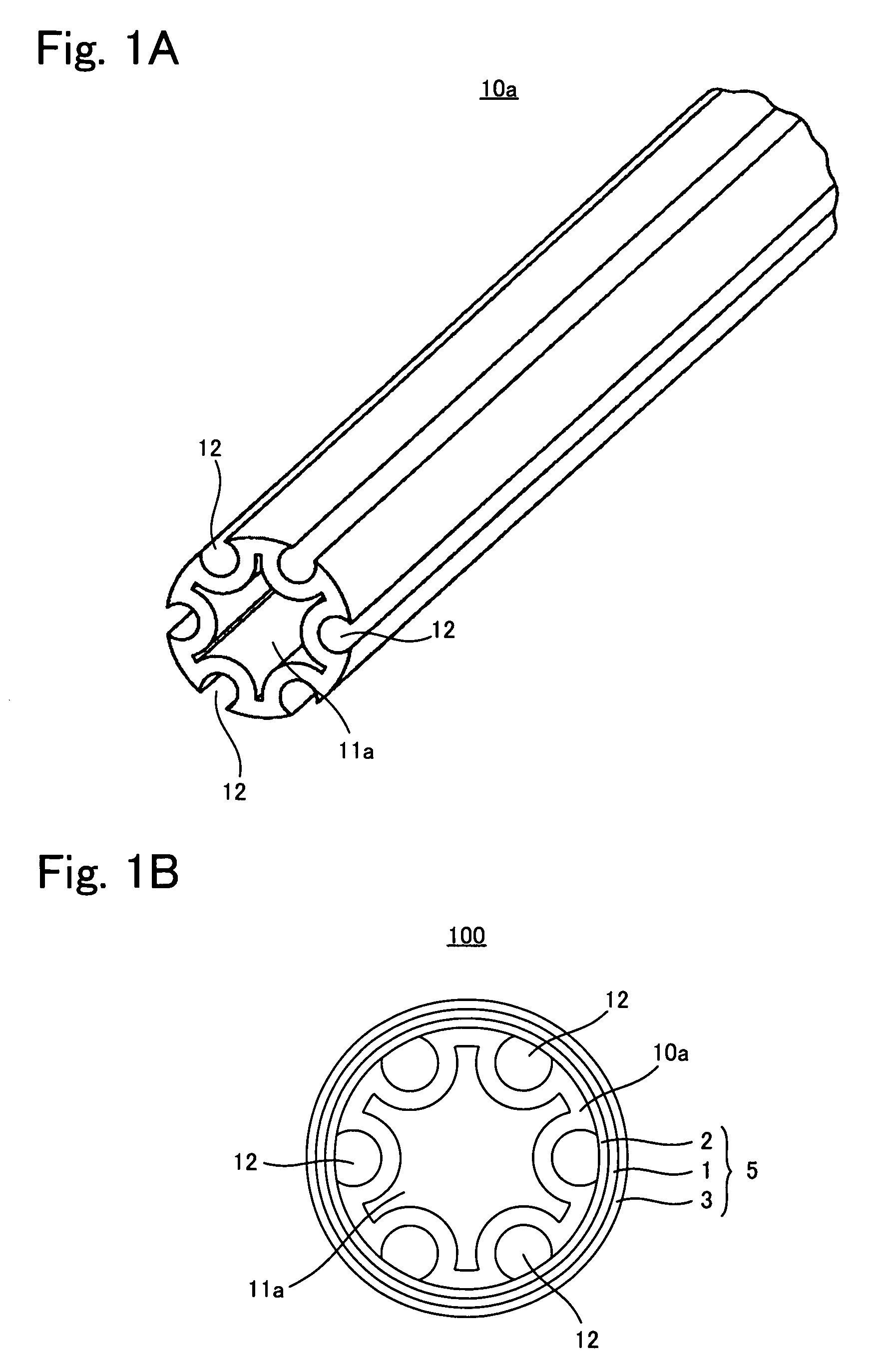
[0033]As shown in FIG. 1A, an internal charge collector 10a is of a hollow shape including a hollow portion 11a, and reaction gas channels 12 each including an opening on its outer circumferential surface are formed in parallel to an axial direction of the internal charge collector. A hollow MEA 5 including hollow electrode 2, an electrolyte membrane 1, and an electrode is arranged outside of the internal charge collector 10a, thereby forming a tubular cell 100 (see FIG. 1B).

[0034]In this manner, the internal charge collector 10a according to the present invention includes the hollow portion 11a. Due to this, if a heat medium is distributed into the hollow portion 11a, heat exchange can be made between the heat medium and the hollow MEA 5 via the internal charge collector 10a at a location quite close to the hollow MEA 5. Moreover, since the reaction gas channels 12 are formed on the outer peripheral surface of the internal charge collector 10 according to the first embodiment, the...

second embodiment

[0039]As shown in FIG. 3A, an internal charge collector 10b is of a hollow shape including a hollow portion 11b, and reaction gas channels 12 each including an opening on its outer circumferential surface are formed on an outer peripheral surface of the internal charge collector. Heat conducting members 15 made of a material (e.g., Cu, At or Pt) having higher heat conductivity than that of constituent elements of the internal charge collector 10b are provided in a thick portion of the internal charge collector 10b. A hollow MEA 5 is provided outside of the internal charge collector 10b, thereby forming a tubular cell 200 (see FIG. 3B).

[0040]In this manner, the internal charge collector 10a according to the second embodiment includes the hollow portion 11b and the reaction gas channels 12, and includes the heat conducting members 15 in its thick portion. Due to this, the internal charge collector 10a has good corrosion resistance. On the other hand, even if the thick portion of the ...


PUM

PropertyMeasurementUnit
electromotive forceaaaaaaaaaa
temperatureaaaaaaaaaa
heat conductivityaaaaaaaaaa

Abstract

A fuel cell capable of improving heat exchange efficiency with respect to tubular fuel cells is provided. A fuel cell includes a hollow electrolyte membrane, hollow electrodes arranged on an inside and an outside of the electrolyte membrane, respectively, and an internal charge collector arranged inside of the electrolyte membrane and the electrodes, wherein the internal charge collector is hollow and made of a nonporous member.

Description

[0001]This is a 371 national phase application of PCT / JP2006 / 317698 filed 31 Aug. 2006, which claims priority of Japanese Patent Application No. 2005-252485 filed 31 Aug. 2005, the contents of which are incorporated herein by reference.FIELD OF THE INVENTION[0002]The present invention relates to a fuel cell including tubular fuel cells, and particularly relates to a fuel cell capable of improving heat exchange efficiency with respect to tubular fuel cells.BACKGROUND OF THE INVENTION[0003]In a conventional polymer electrolyte fuel cell (hereinafter, “PEFC”), electric energy produced by an electrochemical reaction in a membrane electrode assembly (hereinafter, “MEA”) that includes a plane electrolyte membrane and electrodes (a cathode and an anode) arranged on both sides of the electrolyte membrane, respectively is extracted to outside via separators provided on both sides of the MEA, respectively. Attention has now been paid to the PEFC as a power source of a battery car or a portabl...

Claims


Application Information

Patent Timeline
Patent Type & Authority Patents(United States)
IPC IPC(8): H01M8/02H01M8/10
CPCH01M8/0252H01M8/1007H01M8/2415H01M8/04074Y02E60/50H01M8/02H01M8/10H01M8/1065H01M8/2418
Inventor IMANISHI, MASAHIRONAKANISHI, HARUYUKIMURATA, SHIGEAKITAMURA, YOSHIHISA
Owner TOYOTA JIDOSHA KK
Why Eureka
Try Eureka