Surface acoustic wave oscillator and method of varying frequency thereof

a surface acoustic wave and oscillator technology, applied in the field of surface acoustic wave oscillators, can solve the problems of disadvantageous lower disadvantageous narrowing of the variable frequency range, and difficulty in keeping the sn ratio and cn ratio high, so as to achieve a wider bandwidth of oscillating frequencies

Inactive Publication Date: 2010-01-05
SEIKO EPSON CORP
View PDF9 Cites 4 Cited by
  • Summary
  • Abstract
  • Description
  • Claims
  • Application Information

AI Technical Summary

Benefits of technology

[0007]An aspect of the present invention is to achieve a broader bandwidth of a surface acoustic wave oscillator while ensuring the continuousness of the oscillating frequency and to provide a method of changing the frequency without any complicated control.
[0009]According to this aspect of the invention, the first control voltage and second control voltage are applied to the first surface acoustic wave element and the second surface acoustic wave element having different resonance frequencies and connected to the cross-coupled circuit in parallel via the first variable capacitance element and the second variable capacitance element, thereby oscillating the first surface acoustic wave element and the second surface acoustic wave element. The oscillating output obtained by combining the outputs of the first surface acoustic wave element and the second surface acoustic wave element is outputted at the cross-coupled circuit, so the respective oscillating frequencies can be continuously switched to be outputted. This makes it possible to output continuously oscillating frequencies having a broader bandwidth.
[0011]According to this construction, two surface acoustic wave elements stacked on the substrate of the semiconductor chip (integrated circuit) are arranged in parallel, so an area having the size of only two surface acoustic wave elements is required, thereby making it possible to suppress an increase in area and to achieve miniaturization.
[0014]Since the first surface acoustic wave element and the second surface acoustic wave element are connected in parallel to the cross-coupled circuit and have different resonance frequencies, it is possible to achieve a broader bandwidth of the oscillating frequencies of the first surface acoustic wave element and the second surface acoustic wave element and to make the oscillating frequencies to continuously change.

Problems solved by technology

However, with a conventional VCO, it is rather difficult to keep the SN ratio and the CN ratio high with respect to all of the frequency bandwidth, and when the amount of frequency change becomes large, the SN ratio and the CN ratio becomes disadvantageously lower.
On the other hand, when an attempt is made to keep the SN ratio and the CN ratio high, the variable range of the frequency becomes disadvantageously narrower.
However, the use of two VCOs contradicts the miniaturization of communication devices and therefore cannot be considered as a practicable solution.

Method used


Image

  • Surface acoustic wave oscillator and method of varying frequency thereof
  • Surface acoustic wave oscillator and method of varying frequency thereof
  • Surface acoustic wave oscillator and method of varying frequency thereof

Examples


embodiment

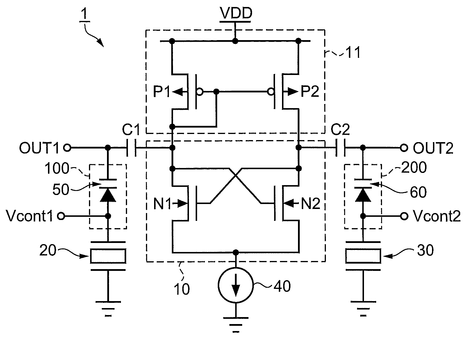
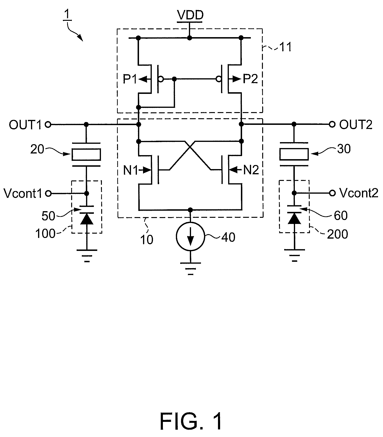
[0036]First, the configuration of the surface acoustic wave oscillator according to this embodiment of the invention will be described with reference to the drawings. FIG. 1 is a circuit diagram illustrating the configuration of the surface acoustic wave oscillator according to this embodiment of the invention.

[0037]As shown in FIG. 1, the surface acoustic wave oscillator 1 includes a cross-coupled circuit 10 and a current mirror circuit 11 each connected to an output terminal OUT1 as a first output terminal and to an output terminal OUT2 as a second output terminal, a first variable capacitance circuit 100 connected to a SAW resonator 20 as a first surface acoustic wave element, to a SAW resonator 30 as a second surface acoustic wave element, and to a control terminal Vcont1 as a first control terminal, and a second variable capacitance circuit 200 connected to a control terminal Vcont2 as a second control terminal.

[0038]The cross-coupled circuit 10 is made up of a Nch transistor N...


PUM


Abstract

A surface acoustic wave oscillator includes: a cross-coupled circuit including first and second active elements differentially connected to first and second output terminals; first and second surface acoustic wave elements having different resonance frequencies and connected to the cross-coupled circuit in parallel; a first variable capacitance circuit including a first variable capacitance element and changing the resonance frequency of the first surface acoustic wave element; and a second variable capacitance circuit including a second variable capacitance element and changing the resonance frequency of the second surface acoustic wave element, wherein the first surface acoustic wave element is connected to the first variable capacitance circuit, the second surface acoustic wave element is connected to the second variable capacitance circuit, and oscillating outputs from combining outputs of the first and second surface acoustic wave elements are outputted by the cross-coupled circuit.

Description

RELATED APPLICATIONS[0001]This application claims priority to Japanese Patent Application Nos. 2006-249405 filed Sep. 14, 2006, 2007-078414 filed Mar. 26, 2007, and 2007-025144 filed Feb. 5, 2007 which are hereby expressly incorporated by reference herein in their entirety.BACKGROUND[0002]1. Technical Field[0003]The present invention relates to a surface acoustic wave oscillator including surface acoustic wave elements having different resonance frequencies and a cross-coupled circuit that differentially connects those elements and to a method of varying the frequency thereof.[0004]2. Related Art[0005]In mobile communication devices communication is performed by, for example, switching multiple channels within the range of the allocated frequency bandwidth. Therefore, it is necessary to perform switching to the designated channel (frequency) at a control channel. Therefore, a synthesizer including a Phase Locked Loop (PLL) circuit has been used. As this PLL circuit, a voltage contro...

Claims


Application Information

Patent Timeline
Patent Type & Authority Patents(United States)
IPC IPC(8): H03B5/12
CPCH03B5/326H03B5/368
Inventor YAJIMA, ARITSUGU
Owner SEIKO EPSON CORP
Why Eureka
Try Eureka