
Coordinate input pen and coordinate input apparatus having the same

a technology of input apparatus and input pen, which is applied in the direction of instruments, mechanical pattern conversion, computing, etc., to achieve the effect of accurate detection of input position

Inactive Publication Date: 2010-01-05
SHARP KK
View PDF11 Cites 8 Cited by
  • Summary
  • Abstract
  • Description
  • Claims
  • Application Information

AI Technical Summary

Benefits of technology

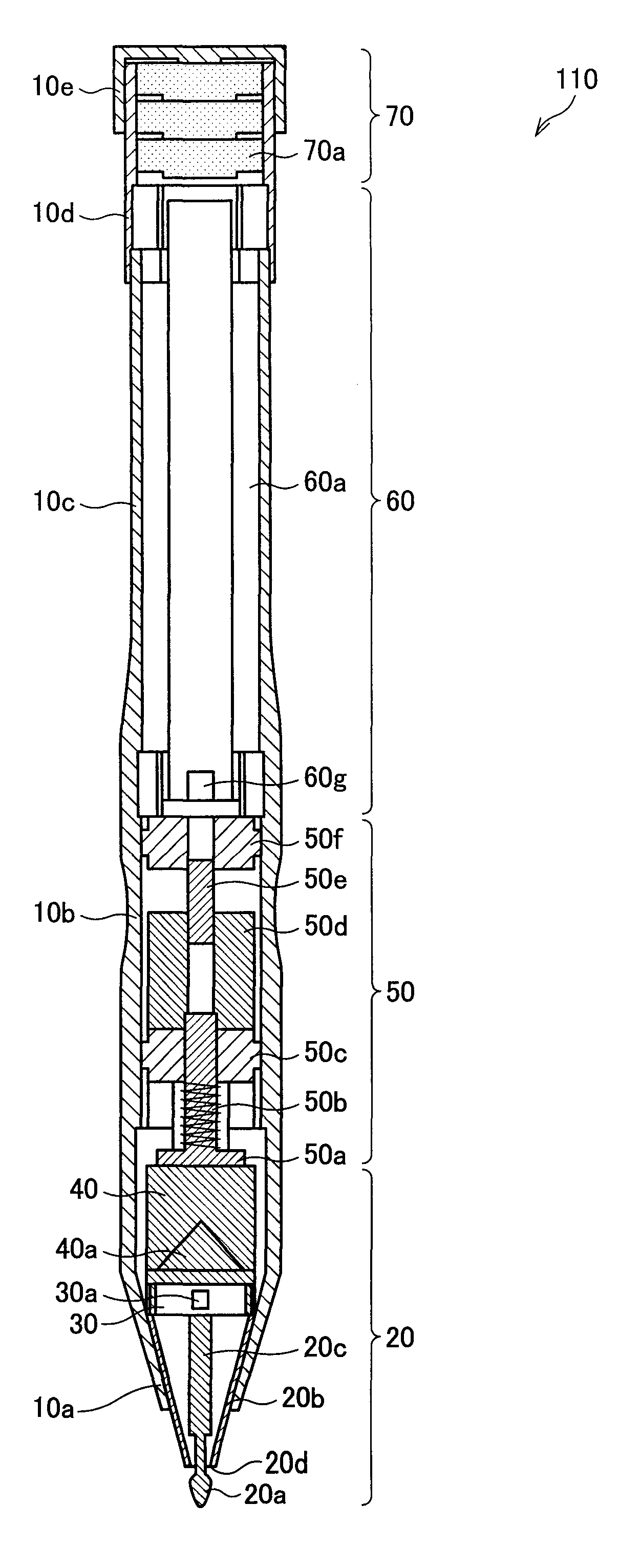
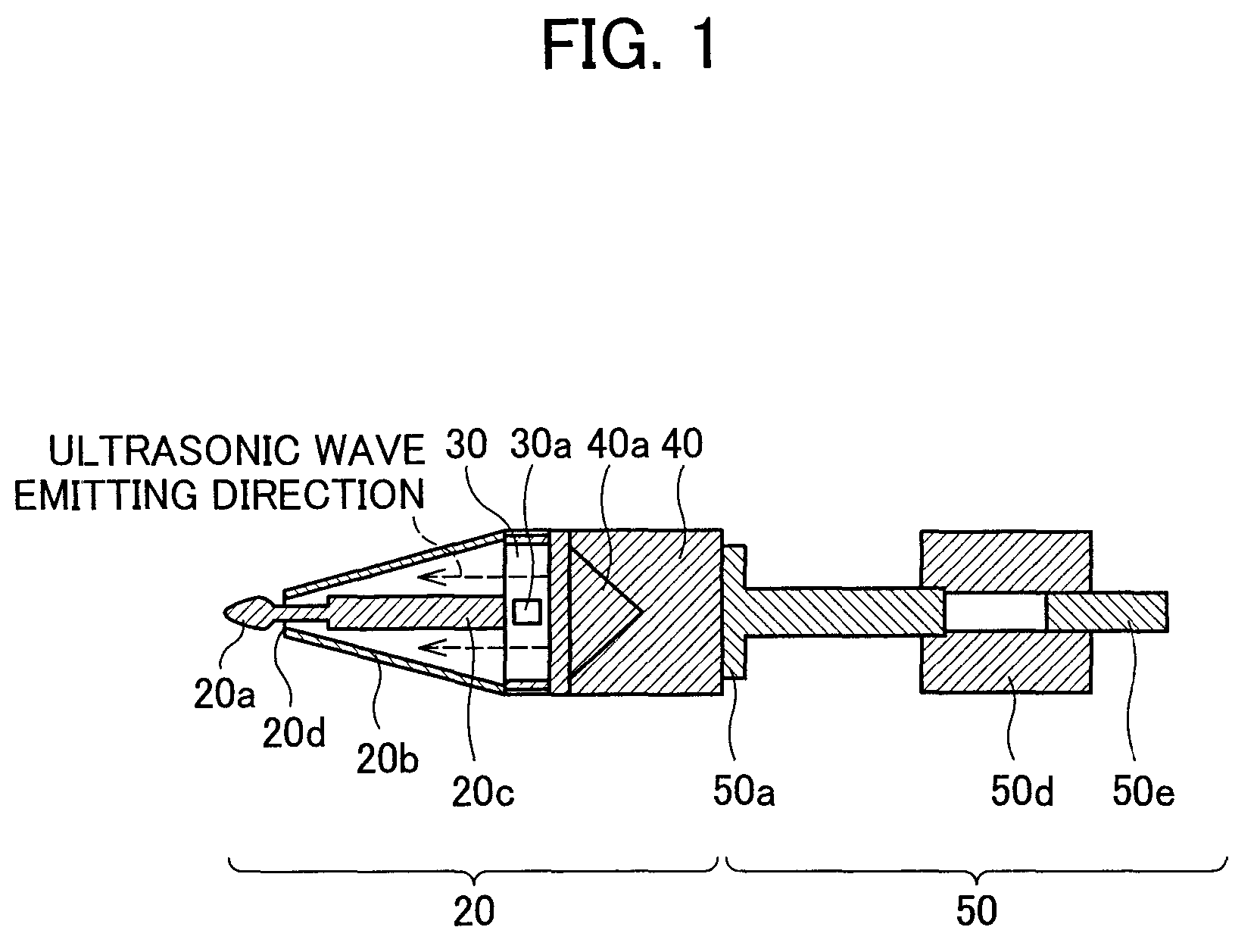
The present invention provides a coordinate input pen and a coordinate input apparatus that can accurately detect input positions regardless of variations in stroke pressure. This is achieved by using an ultrasonic wave to specify the current position of the coordinate input pen. The coordinate input pen includes an ultrasonic wave oscillating section, an ultrasonic wave emitting orifice, and an ultrasonic wave propagation route that ensures a constant distance between the ultrasonic wave oscillating section and the ultrasonic wave emitting outlet. This ensures that the output level of the ultrasonic wave remains constant regardless of the stroke pressure applied on the coordinate input pen. The coordinate input apparatus includes a reception section for receiving the ultrasonic wave emitted from the coordinate input pen and a calculation section for calculating coordinates based on the received ultrasonic wave. The reception section can receive the ultrasonic wave of a constant output level and the calculation section can accurately detect the position specified by the user. The coordinate input pen is designed so that the distance between the ultrasonic wave emitting orifice and the reception section remains constant regardless of the stroke pressure applied on the coordinate input pen. This ensures that the reception section can receive the ultrasonic wave that is oscillated by the coordinate input pen and has a constant output level.

Problems solved by technology

Further, this ultrasonic wave method allows input of exact input position of a pen and exact lines of the pen without providing a special board or a paper.

Method used


Image

  • Coordinate input pen and coordinate input apparatus having the same
  • Coordinate input pen and coordinate input apparatus having the same
  • Coordinate input pen and coordinate input apparatus having the same

Examples


Embodiment Construction

[0029]With reference to FIGS. 1 to 6, the following explains an embodiment of the present invention.

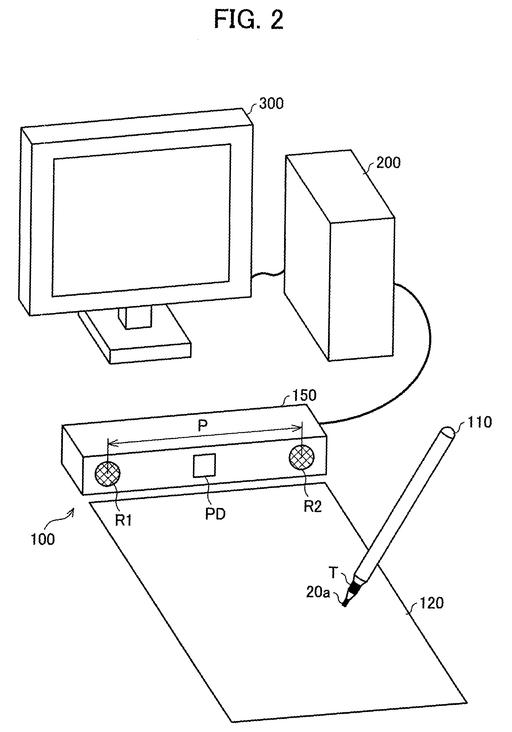
[0030]FIG. 2 is an oblique view schematically illustrating a structure of a coordinate input apparatus according to the embodiment of the present invention. As shown in FIG. 2, a coordinate input apparatus 100 includes a pen-type device (coordinate input pen) 110, an input face 120 (outside), and a reception unit (reception section) 150. Note that, the reception unit 150 is connected with a computer main body 200 and the computer main body 200 is connected with a monitor 300.

[0031]The coordinate input pen 110 is a pointing device based on an ultrasonic wave method for specifying an input position and coordinates. When a user causes a pen point section 20a of the coordinate input pen 110 to touch the input face 120, the coordinate input pen 110 based on the ultrasonic wave method oscillates an ultrasonic wave and an infrared ray. Note that, the detailed structure of the coordinate inpu...


PUM


Abstract

The coordinate input pen according to the present invention is a coordinate input pen for specifying a current position of the coordinate input pen by emitting an ultrasonic wave, including: an ultrasonic wave oscillating section for oscillating the ultrasonic wave for specifying coordinates of the current position; an ultrasonic wave emitting outlet for emitting, to an outside, the ultrasonic wave oscillated by the ultrasonic wave oscillating section; and an ultrasonic wave propagation route which has a fixed length and extends from the ultrasonic wave oscillating section to the ultrasonic wave emitting outlet and is used to propagate the ultrasonic wave to the ultrasonic wave emitting outlet. As a result, it is possible to maintain the output level of the ultrasonic wave oscillated by the ultrasonic wave oscillating section constant regardless of how large a stroke pressure applied on the coordinate input pen is.

Description

[0001]This non-provisional application claims priority under 35 U.S.C. § 119(a) on patent application Ser. No. 185506 / 2005 filed in Japan on Jun. 24, 2005, the entire contents of which are hereby incorporated by reference.FIELD OF THE INVENTION[0002]The present invention relates to a coordinate input pen and a coordinate input apparatus, and more particularly relates to a coordinate input apparatus which causes an ultrasonic wave oscillating section to oscillate ultrasonic waves and detects, based on the ultrasonic waves, coordinates specified by the coordinate input pen.BACKGROUND OF THE INVENTION[0003]As a coordinate input apparatus for use in specifying a position on a screen of a display device or displaying lines such as characters and figures on the display device, various pointing devices such as mouse-type devices, pen-type devices, and track balls have been known.[0004]Recently, pen-type devices (coordinate input pen) using ultrasonic waves have been proposed as pointing de...

Claims


Application Information

Patent Timeline
Patent Type & Authority Patents(United States)
IPC IPC(8): G06F3/033G06F3/041G06F3/043
CPCG06F3/03545G06F3/0433
Inventor AKE, YASUNORI
Owner SHARP KK
Learn More