
Controlling reconfiguration in a cellular communication system

a technology of cellular communication system and control system, applied in multiplex communication, data switching network, synchronisation arrangement, etc., to achieve the effect of easy verification

Active Publication Date: 2010-01-05
TELEFON AB LM ERICSSON (PUBL)
View PDF14 Cites 6 Cited by
  • Summary
  • Abstract
  • Description
  • Claims
  • Application Information

AI Technical Summary

Benefits of technology

The technical effect of this patent is to provide a system and method for changing configurations on a mobile device quickly and efficiently based on user preferences or other factors. By preparing a reconfiguration period indicative of when changes will occur, users can be aware of what modifications they should make to their devices beforehand. Additionally, the use of specific timing codes allows for seamless integration with existing systems and ensures smooth operation during times of transition.

Problems solved by technology

This patent describes cellular communication networks like GSM and UMTS, which use advanced technologies like WCDMA to offer faster internet connections to mobile phones and other devices. These networks require precise knowledge of the configurations of their components, including slots and channels, to ensure proper functioning. One problem addressed in this patent is how to efficiently handle complex changes in network configuration without causing delays for all affected components.

Method used


Image

  • Controlling reconfiguration in a cellular communication system
  • Controlling reconfiguration in a cellular communication system
  • Controlling reconfiguration in a cellular communication system

Examples


Embodiment Construction

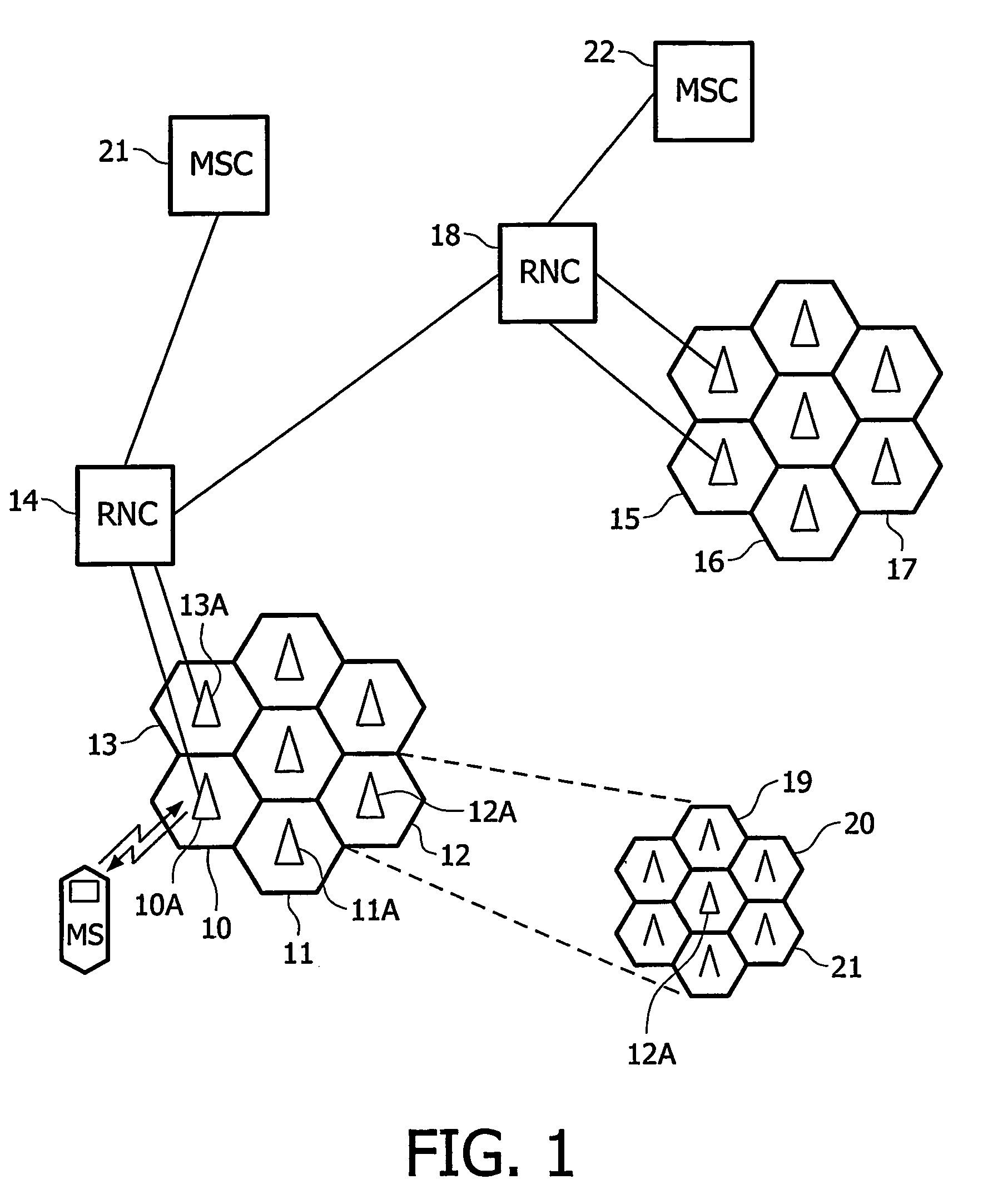
[0032]FIG. 1 shows a simplified schematic view of a cellular system into which the present invention may be incorporated. In mobile telecommunications, a mobile station (MS) such as a mobile telephone communicates over radio channels with base stations. Each base station usually transmits and receives signals over selected radio channels for a particular geographic region known as a cell. The cell often is subdivided into several sectors. Typically a plurality of base stations are connected to a base station controller node, also known as an exchange or a radio network controller node (RNC). One or more RNCs are, in turn, connected to or included with a mobile switching center (MSC). The mobile switching center is usually connected, e.g., via a gateway, to other telecommunication networks, such as the public switched telephone network or to a packet-data network such as the Internet.

[0033]In FIG. 1, the mobile station MS communicates via base station 10A within a geographic cell loc...


PUM


Abstract

In a cellular communication system, for example UMTS using WCDMA, a configuration of radio links is controlled. In a mobile unit, and in a base station, a synchronization counter indicates time codes (CFN) for synchronization of configuration changes across the system. Messages are exchanged between a network controller, the base stations and the mobile units, which messages include a change command (62) for changing a configuration, and a reconfiguration command (61) for changing a current configuration state to a next configuration state at a selected future time code (63). Traditionally a prepared reconfiguration period (67) for such a reconfiguration change was treated as a blocking period for further changes. According to the invention the prepared reconfiguration period is determined, and a prepared reconfiguration period indicator (66) is added to the change command. Hence other configuration changes can be effected during the prepared reconfiguration period.

Description


Claims


Application Information

Patent Timeline
Owner TELEFON AB LM ERICSSON (PUBL)
Learn More