
Head-to-head connector spinal fixation system

a spinal fixation system and head-to-head connector technology, applied in the field of head-to-head connector spinal fixation system, can solve problems such as linear distance between, and achieve the effects of preventing splaying of the head, facilitating implantation, and increasing reliability

Active Publication Date: 2010-01-12
DEPUY SYNTHES PROD INC
View PDF313 Cites 141 Cited by
  • Summary
  • Abstract
  • Description
  • Claims
  • Application Information

AI Technical Summary

Benefits of technology

The present invention is a spinal fixation assembly and an orthopedic implantation device for use in spinal fixation. The invention allows the operating surgeon to select a proper position for a connector independent of local curvature of the spine and the available space along a rod between screws. The invention provides an implantable spinal fixation assembly with a relatively small number of elements, thus resulting in easier implantation and increased reliability. The invention also prevents splaying of the head of the polyaxial screw of the invention due to a combination of engaged convex and concave surfaces.

Problems solved by technology

However, a curvature of the spine and limited available space sometimes results in such an alignment of the screws that a connector must be skipped at a position where the surgeon would place it otherwise.
This can happen when linear distance between two adjacent screws is insufficient for fastening a connector to the rod.

Method used


Image

  • Head-to-head connector spinal fixation system
  • Head-to-head connector spinal fixation system
  • Head-to-head connector spinal fixation system

Examples


Embodiment Construction

[0054]The foregoing and other objects, features and advantages of the invention will be apparent from the following more particular description of preferred embodiments of the invention, as illustrated in the accompanying drawings in which like reference characters refer to the same parts throughout the different views. The drawings are not necessarily to scale, emphasis instead being placed upon illustrating the principles of the invention.

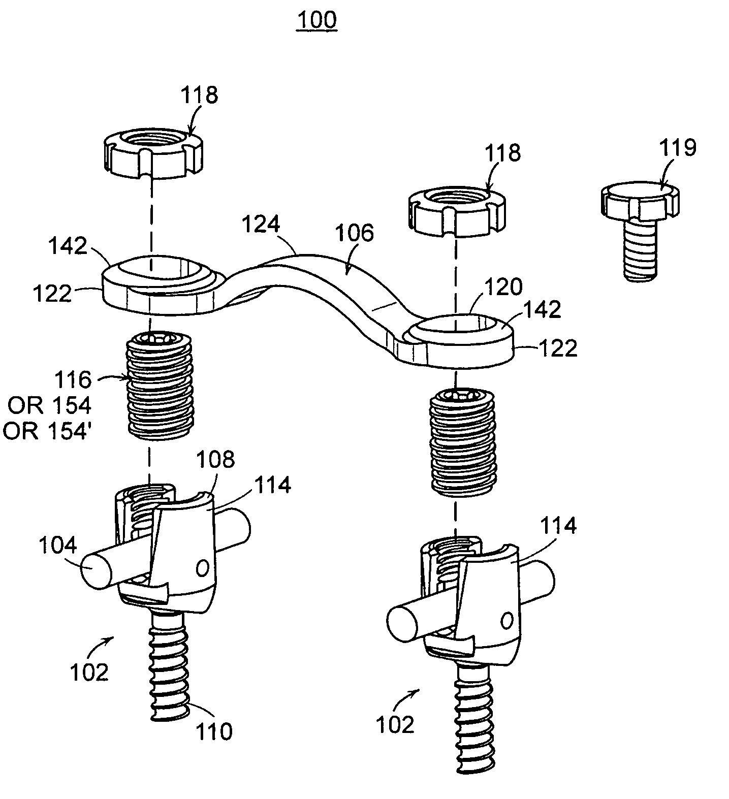
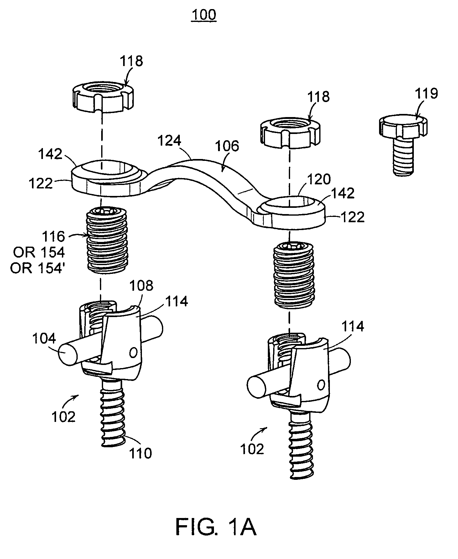
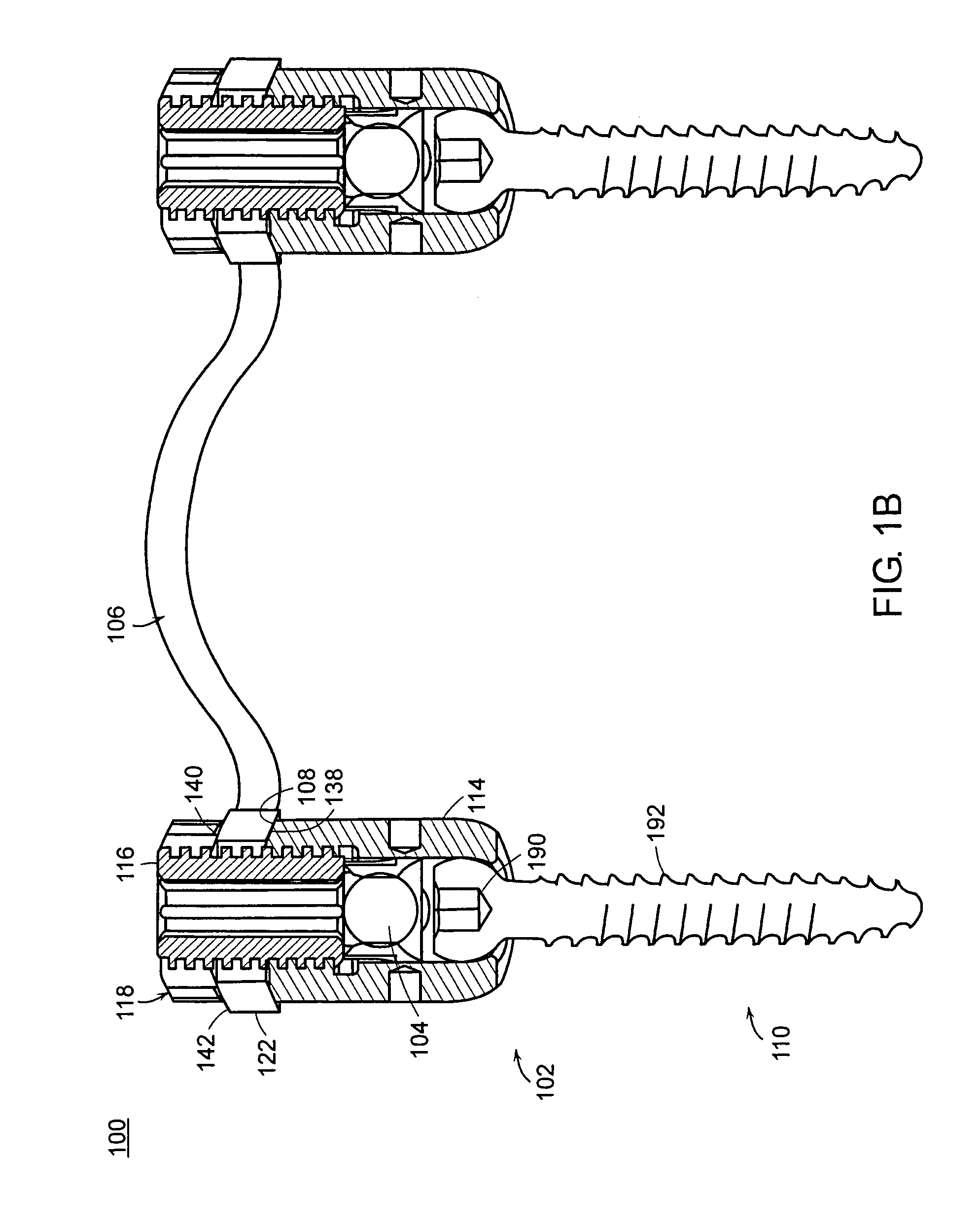
[0055]A spinal fixation assembly of the present invention generally includes one or more bone anchors which are implanted through a portion of a vertebra, for example, the pedicle, lamina, or lateral mass of the vertebra. The bone anchors, described in detail below, may be connected by a spinal fixation element, such as, for example a rod, plate, or cable. The spinal fixation element extends generally along the axis of the spine to fix one or more vertebrae of the spine. One or more connecting plates, described in detail below, can be attached to...


PUM


Abstract

A spinal fixation system comprising at least two bone anchors, a rod connecting the bone anchors and a connecting plate extending from a proximal surface of at least one of the bone anchors. A method of fixing vertebrae relative to each other comprising the steps of: implanting bone anchors in two adjacent vertebrae, each bone anchor having a rod receiving portion; placing a rod in the rod receiving portions, thereby connecting the bone anchors; threadably engaging set screws in the rod receiving portions of at least a portion of the bone anchors, thereby fixing the rod to the bone anchors; mating one end of a connecting plate to a proximal bearing surface of at least a portion of the bone anchors; and engaging a cap with at least a portion of the set screws, thereby fixing the connecting plate to the bone anchors.

Description

BACKGROUND OF THE INVENTION[0001]Spinal fixation systems are implanted during a surgical procedure to treat a variety of problems that include correction of congenital spinal deformities, repair of spinal injuries and fusion of vertebra to stabilize degenerative conditions and alleviate chronic lower back pain. It is well known in the correction of spinal deformities to affix a rod or pair of rods longitudinally to the spinal column with a plurality of screws. It is further common to cross link or interconnect the longitudinal rods to provide additional stabilization by using at least one additional member to horizontally bridge the pair of spinal rods. Devices such as these commonly consist of a brace or connector for providing the desired lateral support. The connector is fastened to each of the spinal rods by clamps or other means located on each end of the connector.[0002]Usually, a surgeon first attaches the screws to the spine in appropriate positions, then attaches each screw...

Claims


Application Information

Patent Timeline
Patent Type & Authority Patents(United States)
IPC IPC(8): A61B17/70A61B17/80
CPCA61B17/7007A61B17/7037A61B17/7049A61B17/7071A61B17/701A61B17/7011A61B17/7032A61B17/7041A61B17/8028
Inventor KALFAS, IAIN H.LAURYSSEN, CARLLUDWIG, STEVENO'BRIEN, MICHAELDOHERTY, THOMASHALL, MARK T.JONES, BRYAN S.KONIECZYNSKI, DAVIDMURPHY, RAYMOND F.
Owner DEPUY SYNTHES PROD INC
Learn More