Correction of alignment and linearity errors in a stylus input system

a linearity and alignment correction technology, applied in the field of computer input devices using stylus input devices, can solve the problems of complex calculations, input problems with the stylus, and further complicated mapping between the digitizer and the lcd, and achieve the effect of flexible and efficien

Inactive Publication Date: 2010-01-12
MICROSOFT TECH LICENSING LLC
View PDF18 Cites 19 Cited by
  • Summary
  • Abstract
  • Description
  • Claims
  • Application Information

AI Technical Summary

Benefits of technology

[0011]Aspects of the invention provide a flexible and efficient method and system for correcting alignment and linearity errors in a device that uses a stylus input device. In a first aspect of the invention, there is a linearity map including an array of data points, wherein each data point comprises data corresponding to known screen coordinates and corresponding input coordinates.

Problems solved by technology

Mapping between the digitizer and the LCD is further complicated by the fact that digitizers and LCD displays often have different resolutions.
Thus, complicated calculations are often required to map from the digitizer to the display.
However, input problems with the stylus can occur because an electromagnetic-based pen digitizer is non-linear, especially close to its edges and corners.
This can be caused by field distortion from the interference of a metal frame and / or other electronics around the edges.
This distortion can create a usability problem because the user may not be able to accurately interact with the computing device, causing the user to become frustrated and stop using the device.
While this may correct the alignment between the digitizer and LCD, linearity problems remain unresolved.
While digitizer manufacturers have included limited linearity correction built-in to digitizer firmware, these digitizers often do not contain enough processing power or memory to fully compensate areas of high distortion.

Method used


Image

  • Correction of alignment and linearity errors in a stylus input system
  • Correction of alignment and linearity errors in a stylus input system
  • Correction of alignment and linearity errors in a stylus input system

Examples


Embodiment Construction

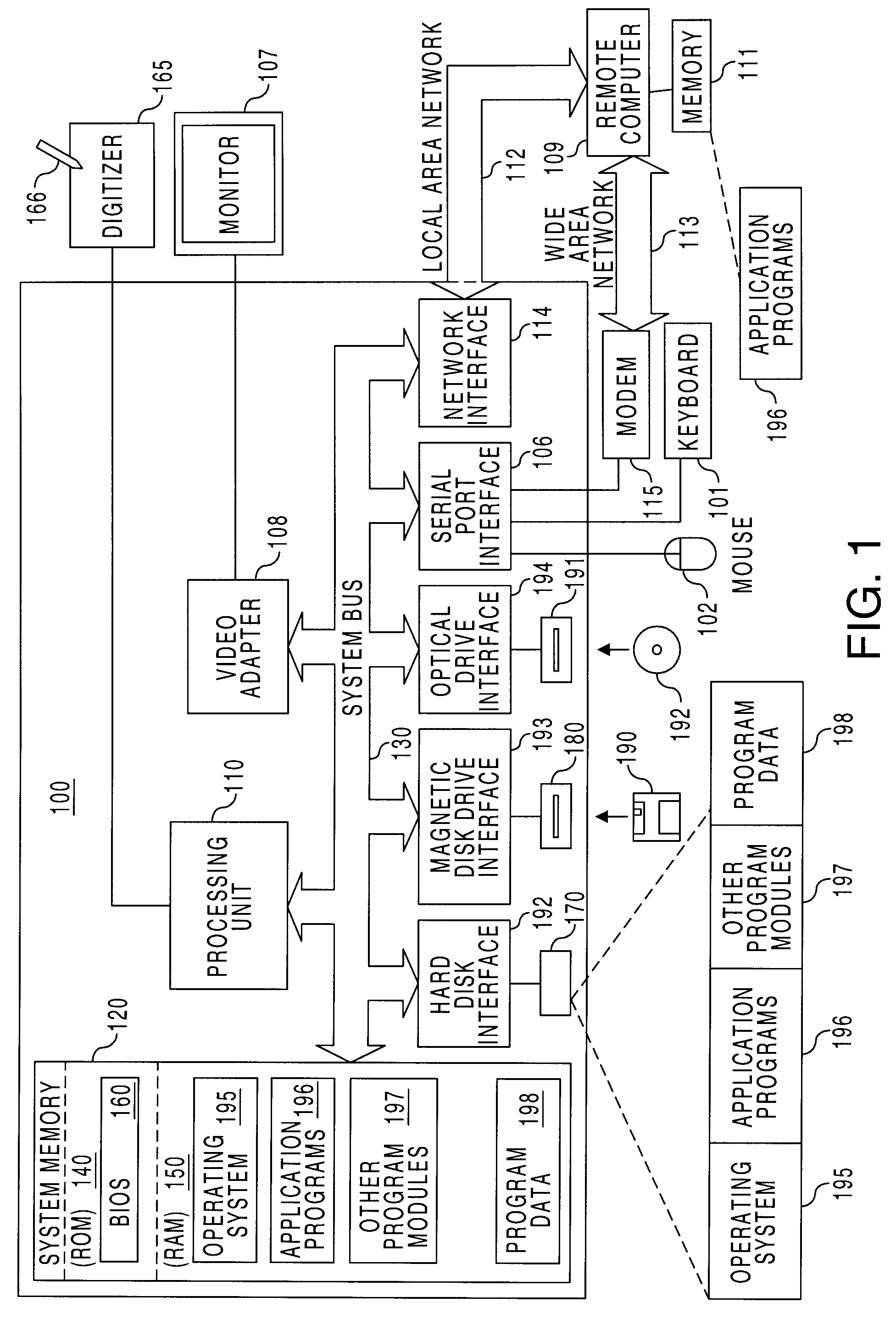
[0030]Embodiments and aspects of the present invention may be more readily described with reference to FIGS. 1-14. FIG. 1 illustrates a schematic diagram of a conventional general-purpose digital computing environment that can be used to implement various aspects of the present invention. In FIG. 1, a computer 100 includes a processing unit 110, a system memory 120, and a system bus 130 that couples various system components including the system memory to the processing unit 110. The processing unit 110 may include one or more processors. The system bus 130 may be any of several types of bus structures including a memory bus or memory controller, a peripheral bus, and a local bus using any of a variety of bus architectures. The system memory 120 includes read only memory (ROM) 140 and random access memory (RAM) 150.

[0031]A basic input / output system 160 (BIOS), containing the basic routines that help to transfer information between elements within the computer 100, such as during sta...


PUM


Abstract

A method and system for correcting alignment and linearity errors in devices using a finger or stylus input device with a display device interactively coupled to a digitizer is disclosed. Touching intersections in a calibration grid on the display device may be performed to create a linearity map. Subsequently, detected stylus input is mapped to a sector in the linearity map, and resultant screen coordinates are calculated using ratios within a reference rectangle corresponding to the detected stylus input and the mapped sector.

Description

[0001]This application is a continuation of and claims priority from application Ser. No. 10 / 799,636, filed Mar. 15, 2004, which is a continuation of application Ser. No. 09 / 918,482, filed Aug. 1, 2001, now U.S. Pat. No. 6,727,896, issued Apr. 27, 2004, all of the same title.FIELD OF THE INVENTION[0002]One or more aspects of the invention relates to computing devices using a stylus input device. More specifically, aspects of the invention relate to a method and system for correcting alignment and linearity errors when a stylus digitizer is used in combination with a display screen to provide input to a computing system.BACKGROUND OF THE INVENTION[0003]Portable computing systems, such as personal digital assistants (PDA), often have a stylus or other pen-like input device for receiving user input. For instance, a user may use a pen-like stylus to interact with a PDA by pressing the stylus against a display screen. The display screen is generally an LCD display. Depending on the type ...

Claims


Application Information

Patent Timeline
Patent Type & Authority Patents(United States)
IPC IPC(8): G06F3/041G06K11/06G06F3/033G06F3/045G06F3/046
CPCG06F3/0418G06F3/045G06F3/046G06F3/04186
Inventor TSANG, MICHAEL H.
Owner MICROSOFT TECH LICENSING LLC
Why Eureka
Try Eureka