
Hybrid spectral domain optical coherence tomography line scanning laser ophthalmoscope

a laser ophthalmoscope and optical coherence technology, applied in the field of optical imaging, can solve the problems of limited diagnostic utility of this powerful imaging modality and the inability to accurately assess the transverse eye motion, and achieve the effects of simple, compact instruments, and enhanced diagnostic utility of o

Inactive Publication Date: 2010-01-19
PHYSICAL SCI
View PDF69 Cites 42 Cited by
  • Summary
  • Abstract
  • Description
  • Claims
  • Application Information

AI Technical Summary

Benefits of technology

"The invention is a system that combines an OCT system and an LSLO system to provide images of the retina of an eye using a single compact instrument. The system features a wide-field en face retinal LSLO and SDOCT imaging modes that require no more than 600 microwatts of broadband illumination. The system can be used in clinical ophthalmic diagnostics and emergency medicine. The integration of the two imaging modes allows for quicker assessment of pathologies in linked, complementary views with a simple compact instrument. The system can also be used to guide the use of OCT imaging with a 3 mm pupil. The patent describes an optical apparatus and a method for imaging the retina of an eye using both OCT and LSLO modes."

Problems solved by technology

Although B-scan image distortion by involuntary eye movement is reduced, transverse eye motion remains an issue for 3-D imaging and individual scan registration.
Yet without precise knowledge of the OCT scan coordinates within the live fundus image to guide scan acquisition and interpretation, the diagnostic utility of this powerful imaging modality is limited.

Method used


Image

  • Hybrid spectral domain optical coherence tomography line scanning laser ophthalmoscope
  • Hybrid spectral domain optical coherence tomography line scanning laser ophthalmoscope
  • Hybrid spectral domain optical coherence tomography line scanning laser ophthalmoscope

Examples


Embodiment Construction

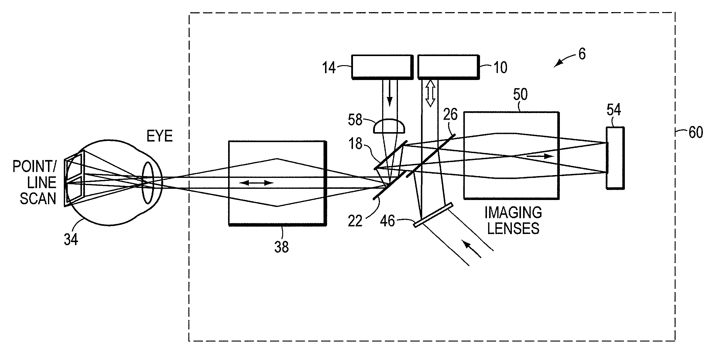
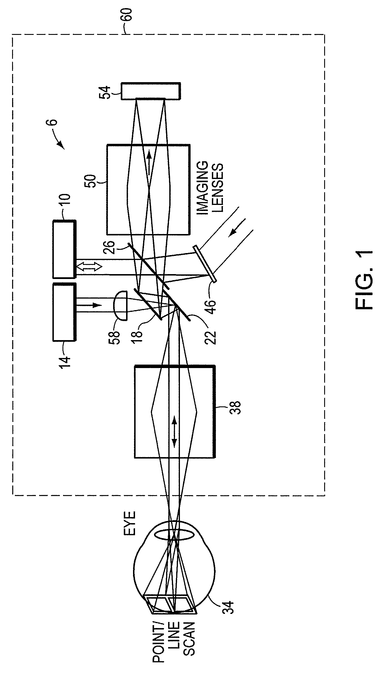
[0033]FIG. 1 shows an embodiment of an imaging apparatus 6 that can provide line scanning laser ophthalmoscope (LSLO) images and Optical Coherence Tomography (OCT) image. The imaging apparatus 6 can be converted between a LSLO mode and a OCT mode without the use of moving parts. Instead, a system of optical elements are implemented to combine the beam paths of the OCT and the LSLO and to scan an eye 34. A first source 10 provides a first beam of light for the OCT mode and a second source 14 provides a second beam of light for the LSLO mode. The imaging system 6 can operate in the LSLO and the OCT mode using optical elements 18, 22, and 26.

[0034]When the imaging apparatus 6 is operating in the OCT mode, the beam of light from the OCT light source 10 travels to a first surface of the optical element 26, which directs the light to a first surface of optical element 18. The line can be redirected to optical element 22, which scans the beam of light along the retina of the eye 34. In som...


PUM


Abstract

An apparatus for imaging an eye includes a housing and a system of optical components disposed in the housing. The apparatus is capable of operating in a line scanning laser ophthalmoscope (LSLO) mode and an optical coherence tomography (OCT) mode. The system of optical components can include a first source to provide a first beam of light for the OCT mode and a second source to provide a second beam of light for the LSLO mode. In the OCT mode, a first optic is used that (i) scans, using a first surface of the first optic, the first beam of light along a retina of an eye in a first dimension, and (ii) descans, using the first surface, a first light returning from the eye in the first dimension to a detection system in the OCT mode. In the LSLO mode, the first optic is used where the second beam of light passes through a second surface of the first optic.

Description

CROSS-REFERENCE TO RELATED APPLICATION[0001]This application claims the benefit of and priority to U.S. provisional patent application No. 60 / 796,387 filed May 1, 2006, which is owned by the assignee of the instant application and the disclosure of which is incorporated herein by reference in its entirety.STATEMENT OF GOVERNMENT INTEREST[0002]This invention was made with government support under Air Force Contract No. FA9550-05-C-0181. The government may have certain rights in the invention.FIELD OF THE INVENTION[0003]This invention relates generally to optical imaging, and more particularly, to a device that combines a line-scanning laser ophthalmoscope and a spectral domain optical coherence tomography system for retinal imaging.BACKGROUND OF THE INVENTION[0004]Fundus and retinal imaging are important diagnostics in ophthalmology. Advanced imaging technologies now exist to detect tissue changes that occur due to retinal injuries not discernable with fundus photography. For example...

Claims


Application Information

Patent Timeline
Patent Type & Authority Patents(United States)
IPC IPC(8): A61B3/10
CPCA61B3/102A61B3/1025G01B9/02091G01B9/02044G01B9/0203
Inventor FERGUSON, R. DANIELHAMMER, DANIEL X.IFTIMIA, NICUSOR V.BIGELOW, CHAD
Owner PHYSICAL SCI
Learn More