Device for treating a medical liquid

Active Publication Date: 2010-01-19
FRESENIUS MEDICAL CARE DEUTSCHLAND GMBH
View PDF28 Cites 152 Cited by
  • Summary
  • Abstract
  • Description
  • Claims
  • Application Information

AI Technical Summary

Benefits of technology

[0009]It is therefore the object of the present invention to further develop a generic apparatus comprising a fluid treatment machine and a cassette

Problems solved by technology

The design of such blood tubing systems is very complex in manufacture and handling, with the corresponding effort naturally being extremely time consuming with more complex systems such

Method used


Image

  • Device for treating a medical liquid
  • Device for treating a medical liquid
  • Device for treating a medical liquid

Examples


Embodiment Construction

[0029]Further scope of applicability of the present invention will become apparent from the detailed description given hereinafter. However, it should be understood that the detailed description and specific examples, while indicating preferred embodiments of the invention, are given by way of illustration only, since various changes and modifications within the spirit and scope of the invention will become apparent to those skilled in the art from this detailed description.

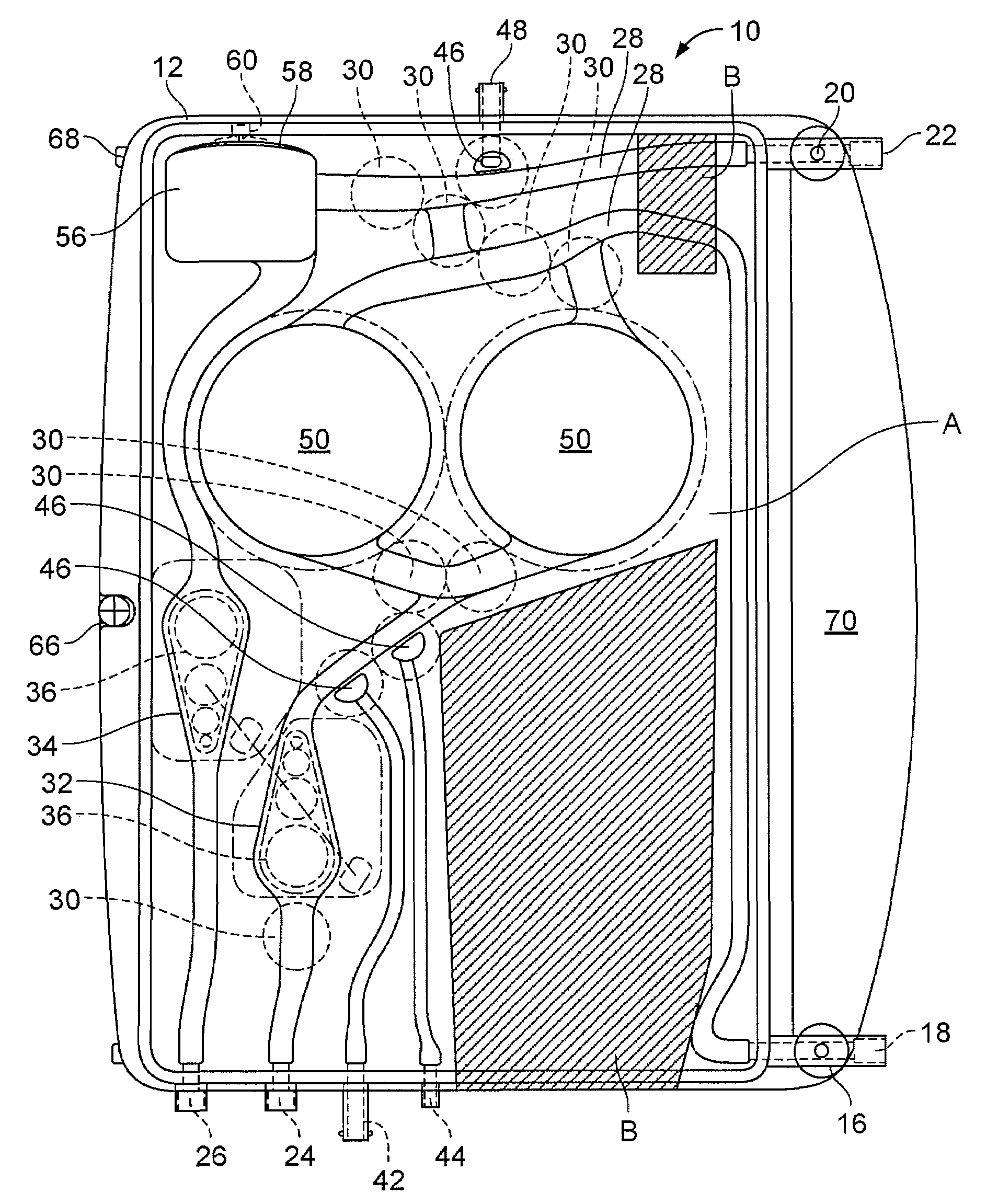
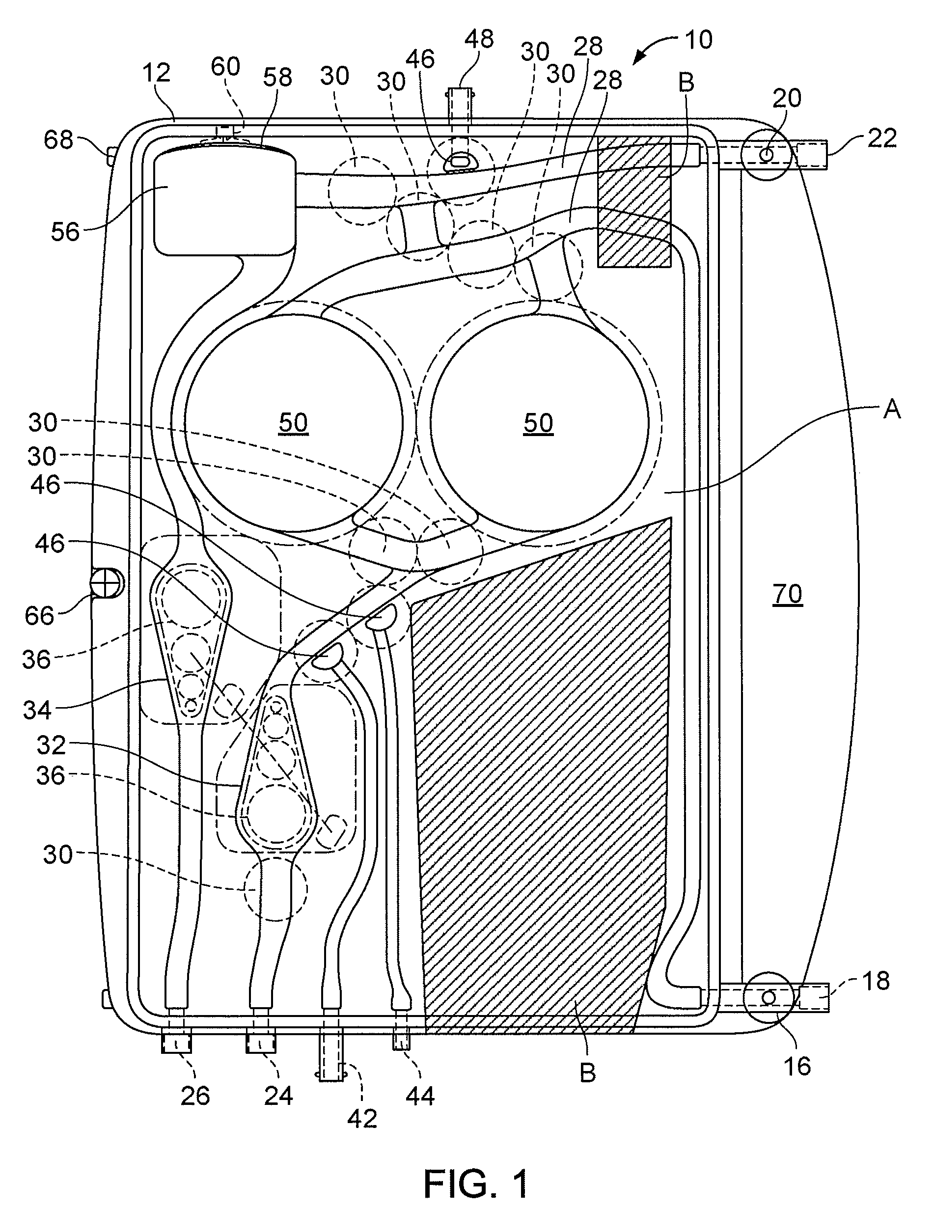
[0030]In FIG. 1, a cassette 10 in accordance with an embodiment variant of the present invention is shown which can be used in this embodiment for standard hemodialysis. In FIG. 1, the surface of the cassette 10 is divided into a hatched region B (two partial areas) and a non-hatched region A. Both the surface of the cassette 10 and the surface of the associated machine block (cf. FIG. 7) are divided into the covering surface regions A and B, with components of actuators or sensors to be coupled, which are common...


PUM

PropertyMeasurementUnit
Fractionaaaaaaaaaa
Shapeaaaaaaaaaa
Radiusaaaaaaaaaa

Abstract

An apparatus for the treatment of a medical liquid has a liquid treatment machine and a cassette that is insertable in the machine. The cassette has a rigid base body with fitted chambers and passages and a foil that covers the chambers and passages. Actuators and sensors are arranged in the liquid treatment machine for the operation of the apparatus with the inserted cassette such that cassettes are insertable in different integration shapes.

Description

[0001]This is a nationalization of PCT / EP03 / 05377 filed May 22, 2003 and published in German.BACKGROUND OF THE INVENTION[0002]1. Field of Invention[0003]The invention relates to an apparatus for the treatment of a medical fluid comprising a fluid treatment machine and a cassette insertable therein substantially consisting of a rigid base body of the cassette with fitted chambers and passages and a foil covering them.[0004]2. Description of the Prior Art[0005]Corresponding cassettes are used in medical engineering, in particular to convey dialysis fluid, blood and the like. Cassettes of this type are described e.g. in DE 198 37 667, WO 84 / 02473, WO 98 / 22165 or WO 00 / 33898.[0006]A cassette is, for example, thus known from DE 198 37 667 A1 which consists of a base body of a cassette with fitted chambers and passages and which is closed by a flexible foil to cover the passages and chambers. It is already described there that the cassette is inserted into a special receiving chamber, e.g...

Claims


Application Information

Patent Timeline
IPC IPC(8): A61M1/10B01D65/00A61J1/10A61M1/02A61M1/14A61M1/34A61M1/36A61M60/113A61M60/268A61M60/37A61M60/427A61M60/847
CPCA61M1/1037A61M1/3496A61M1/3621A61M1/367A61M1/16A61M2205/128A61M2205/12A61M2205/122A61M2205/3331A61M60/113A61M60/268A61M60/43A61M60/847A61M60/427A61M60/37A61M1/36225A61M1/36224A61M1/3401A61M1/152A61M1/15632A61M1/362264A61M1/1524A61M1/362265A61M1/362223A61M1/362261A61M1/1601A61M1/1621A61M2202/0413A61M2205/126
Inventor BEDEN, JOSEFHAHMANN, UWEHERKLOTZ, MARTINLAUER, MARTINMANKE, JOACHIMSCHEUNERT, PETERWEIS, MANFREDBONGERS, ALEXANDER
Owner FRESENIUS MEDICAL CARE DEUTSCHLAND GMBH
Why Eureka
Try Eureka