Method and system for extending coverage of WLAN access points via optically multiplexed connection of access points to sub-stations

a technology of optical multiplexing and access points, applied in the field of wireless communication systems, can solve the problems of cumbersome installation and maintenance of aps in conventional wireless lan systems, and achieve the effect of highest communication efficiency in the area

Inactive Publication Date: 2010-01-19
INTERDIGITAL PATENT HLDG INC
View PDF20 Cites 49 Cited by
  • Summary
  • Abstract
  • Description
  • Claims
  • Application Information

AI Technical Summary

Benefits of technology

[0013]As described above, in conventional configurations, the terminal accommodation capacity of the area A is twenty, while the terminal accommodation capacity of the area B is thirty. Therefore, when the area A has twenty terminals and the area B has thirty terminals, the communication efficiency in the area is highest.
[0014]However, in the case of wireless LAN services in, for example, a public place, unlike offices, the number of terminals in each area always varies. Therefore, the number of terminals present in each of the areas A and B is rarely equal to its accommodation capacity. It is likely that a larger number of terminals than the accommodation capacity are concentrated in one area while a much smaller number of terminals than the accommodation capacity are present in the other area. More specifically, for example, the area A has forty terminals while the area B has only ten terminals. In this case, although a total of five APs are present and therefore the total accommodation capacity is fifty, communication quality is extremely lowered in the area A. Thus, in conventional configurations, the efficiency of use of an AP may be reduced.

Problems solved by technology

Therefore, it is cumbersome to install and maintain an AP in conventional wireless LAN systems.

Method used


Image

  • Method and system for extending coverage of WLAN access points via optically multiplexed connection of access points to sub-stations
  • Method and system for extending coverage of WLAN access points via optically multiplexed connection of access points to sub-stations
  • Method and system for extending coverage of WLAN access points via optically multiplexed connection of access points to sub-stations

Examples


embodiment 1

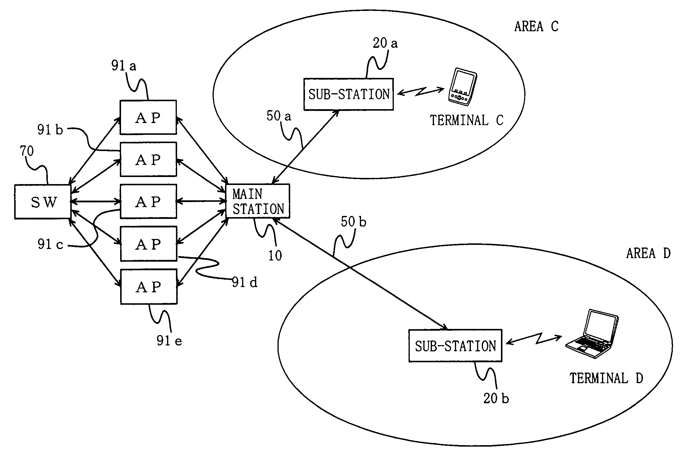
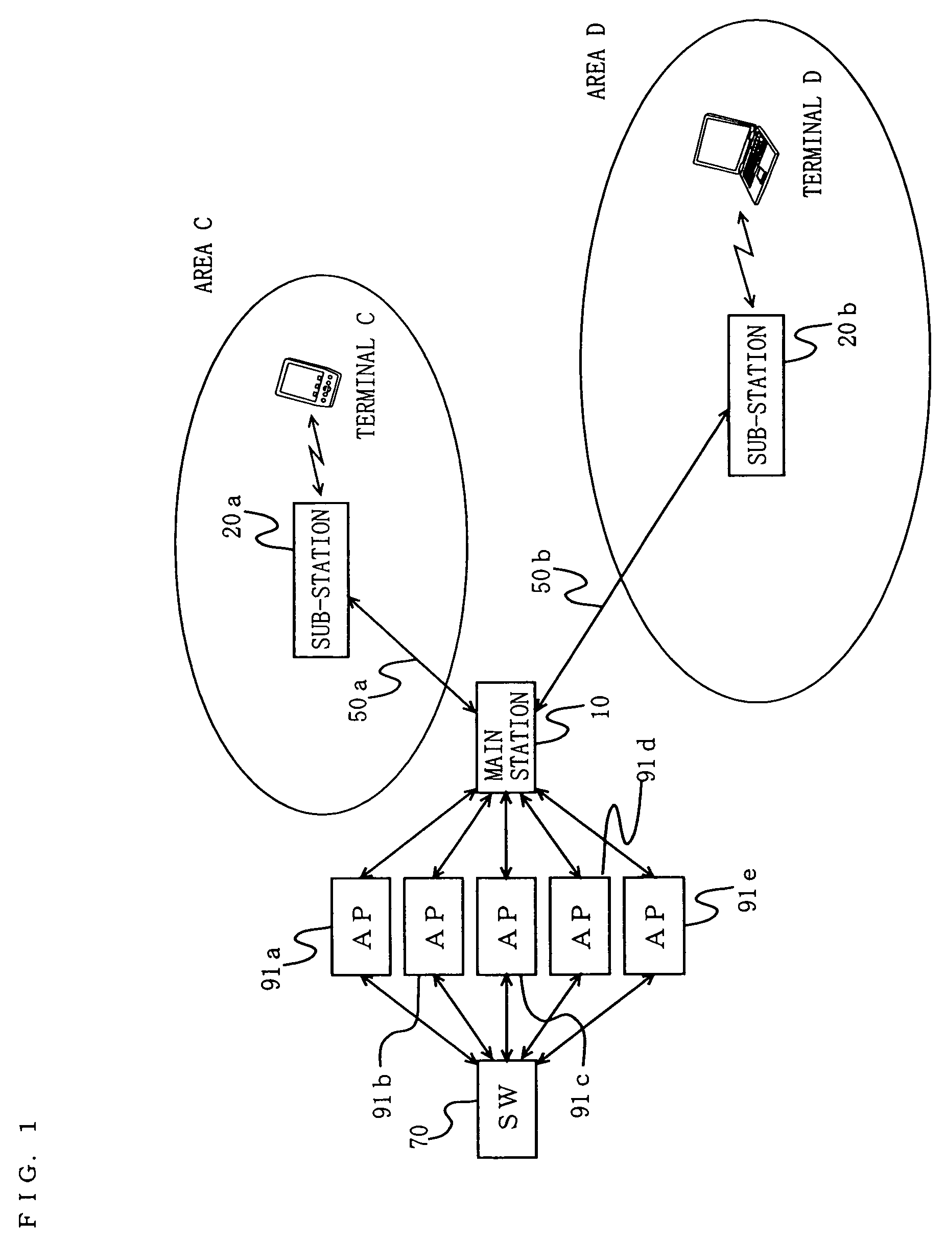
[0166]Hereinafter, an entire structure of a wireless communication system according to Embodiment 1 of the present invention will be described with reference to the accompanying drawings. FIG. 1 is a block diagram showing the entire configuration of the wireless communication system.

[0167]The wireless communication system of Embodiment 1 has areas C and D (in the claims, the areas C and D are each referred to as a wireless communication area, and collectively referred to as a local area), and comprises a main station 10, sub-stations 20a and 20b, optical fiber transmission paths 50a and 50b, a network switch (abbreviated as SW in FIG. 1) 70, access points (abbreviated as AP in FIG. 1) 91a to 90e, and terminals C and D. Note that the terminals C and D are representative terminals which are present in the respective areas. Therefore, a number of terminals are present in the actual areas C and D in addition to the terminals C and D.

[0168]The area C is an area in which the sub-station 2...

embodiment 2

[0270]Hereinafter, an entire configuration of a wireless communication system according to Embodiment 2 of the present invention will be described with reference to the drawings. Note that the entire configuration of the wireless communication system of Embodiment 2 is similar to that of Embodiment 1, and therefore, FIG. 1 is referenced.

[0271]The SW 70 and the APs 91a to 91e are similar to those of Embodiment 1 and will not be explained. Also, the sub-stations 20a and 20b are similar to those of Embodiment 1, and therefore, FIG. 3 is referenced.

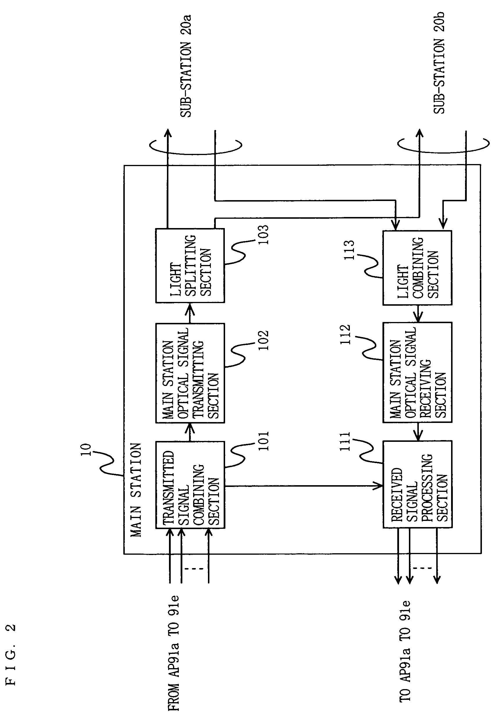
[0272]Here, a main station 10 of the wireless communication system of Embodiment 2 will be described. The main station 10 of Embodiment 2 converts an electrical signal type wireless LAN signal input from the APs 91a to 91e to an optical signal, and selectively outputs the optical signal to each of the sub-stations 20a and 20b. More specifically, the main station 10 outputs the optical signal to both or one of the sub-station 20a and the sub-s...

embodiment 3

[0326]Hereinafter, an entire configuration of a wireless communication system according to Embodiment 3 of the present invention will be described with reference to the drawings. FIG. 17 is a block diagram showing the entire configuration of the wireless communication system of Embodiment 3. The wireless communication system of Embodiment 3 is different from that of Embodiment 1 in that an area G is also present in a main station 30. The other elements are similar to those of Embodiment 1 and will not be explained.

[0327]A SW 70 and APs 91a to 91e of Embodiment 3 are similar to those of Embodiment 1 and will not be explained. The configuration of sub-stations 20a and 20b of Embodiment 3 is similar to that of Embodiment 1 of FIG. 3 and will not be explained.

[0328]Here, the main station 30 of Embodiment 3 will be described with reference to the drawings. FIG. 18 is a block diagram showing a configuration of the main station 30 of Embodiment 3. The main station 30 is the same as the mai...


PUM


Abstract

A SW (70) receives an Ethernet® signal from an outside of areas E and F. The SW (70) selects and outputs the obtained Ethernet® signal to any one of APs (91a to 91e) in accordance with a network structure managed by the SW (70). The AP (91a to 91e) converts the Ethernet® signal to an electrical signal type wireless LAN signal, which is in turn output to a main station (10). The main station (10) frequency-multiplexes the signal output from each of the APs (91a to 91e), and converts the signal to an optical signal, which is in turn output to sub-stations (20a and 20b). The sub-station (20a and 20b) transmits the signal transmitted from the main station (10) to a terminal in the form of a wireless radio wave. Thereby, when a plurality of communication areas are present, the accommodation capacity of an AP can be effectively utilized in each communication area.

Description

TECHNICAL FIELD[0001]The present invention relates to a wireless communication system. More particularly, the present invention relates to a system which enables a wireless communication terminal present in a local area to communicate with a network outside the local area.BACKGROUND ART[0002]A conventional, general wireless LAN system is disclosed in “Nikkei Communications”, issued on Sep. 2, 2002, Nikkei Business Publications, Inc. (p. 89, FIGS. 1-2).[0003]FIG. 39 is a block diagram showing an exemplary configuration of the conventional wireless LAN system. The wireless LAN system has two communication areas A and B, an SW 70, electric cables 80a to 80e, access points (hereinafter referred to as APs) 90a to 90e, and terminals A and B. Also, the wireless LAN system is connected to the SW 70 to an external network (not shown).[0004]The SW 70 switches an Ethernet® signal, which is input from an external network to the wireless LAN system, to each of the APs 90a to 90e. The electric ca...

Claims


Application Information

Patent Timeline
Patent Type & Authority Patents(United States)
IPC IPC(8): H04B7/15H04J14/00H04B10/27H04J14/02H04L12/28H04W4/18H04W16/02H04W40/34H04W72/04H04W84/12H04W88/04H04W88/08H04W92/02
CPCH04B10/25754H04W4/18H04W84/12H04W88/04H04W92/02H04L12/28H04L12/46
Inventor UTSUMI, KUNIAKIYAMAMOTO, HIROAKIMASUDA, KOUICHINIIHO, TSUTOMUNAKASO, MARIKOSASAI, HIROYUKI
Owner INTERDIGITAL PATENT HLDG INC
Why Eureka
Try Eureka