Fiber optic connector for coupling laser energy into small core fibers, and termination method therefor

a fiber optic connector and laser energy technology, applied in glass making apparatus, instruments, manufacturing tools, etc., can solve the problems of reducing the efficiency of the delivery system, difficult to couple light to the fiber, and limiting the amount of energy that can be delivered

Inactive Publication Date: 2009-06-02
BROWN JOE D
View PDF27 Cites 42 Cited by
  • Summary
  • Abstract
  • Description
  • Claims
  • Application Information

AI Technical Summary

Benefits of technology

[0011]It is accordingly a first objective of the invention to provide a fiber termination arrangement for coupling a laser to an optical fiber, in which the percentage of radiation that couples to the fiber is increased by increasing an area of the coupling end of the fiber.
[0012]It is a second objective of the invention to provide a fiber termination arrangement for coupling a laser to an optical fiber that increases an effective coupling area of the fiber and that also provides enhanced dissipation of radiation incident on the surface that does not couple to the fiber.
[0013]It is a third objective of the invention to provide a fiber termination arrangement for coupling a laser to an optical fiber, that not only increases the effective coupling area of the fiber but that also minimizes creation of higher order propagation modes within the fiber.

Problems solved by technology

In optical fiber applications where fiber size or flexibility is important, a problem often arises in that it is difficult to couple light to the fiber, either because the fiber has a core diameter smaller than the focused spot of the laser source, the focused spot is not precisely aligned with the fiber, and / or the acceptance angle is too small to accept all of the focused radiant energy.
This reduces the efficiency of the delivery system, limiting the amount of energy that can be delivered, and in addition raises the possibility of damage to the fiber termination and / or connector, or of unwanted coupling of light to the cladding of the fiber, which can cause damage downstream from the termination.
However, the use of tapers has the disadvantage of enabling light to enter the fiber at increased angles of incidence, thereby creating higher order propagation modes which limit the bend performance of the fiber or alter the output.
However, it has been very difficult in practice to implement the heat fusion proposed by Griffin in practice.
In addition, by attaching a beam block to the quartz ferrule in order to prevent damage during fusion, Griffin fails to provide a way to adequately deflect or dissipate radiation that fails to couple to the core through the quartz ferrule, and therefore the Griffin arrangement still presents a risk of damage to the connector.

Method used


Image

  • Fiber optic connector for coupling laser energy into small core fibers, and termination method therefor
  • Fiber optic connector for coupling laser energy into small core fibers, and termination method therefor
  • Fiber optic connector for coupling laser energy into small core fibers, and termination method therefor

Examples


Embodiment Construction

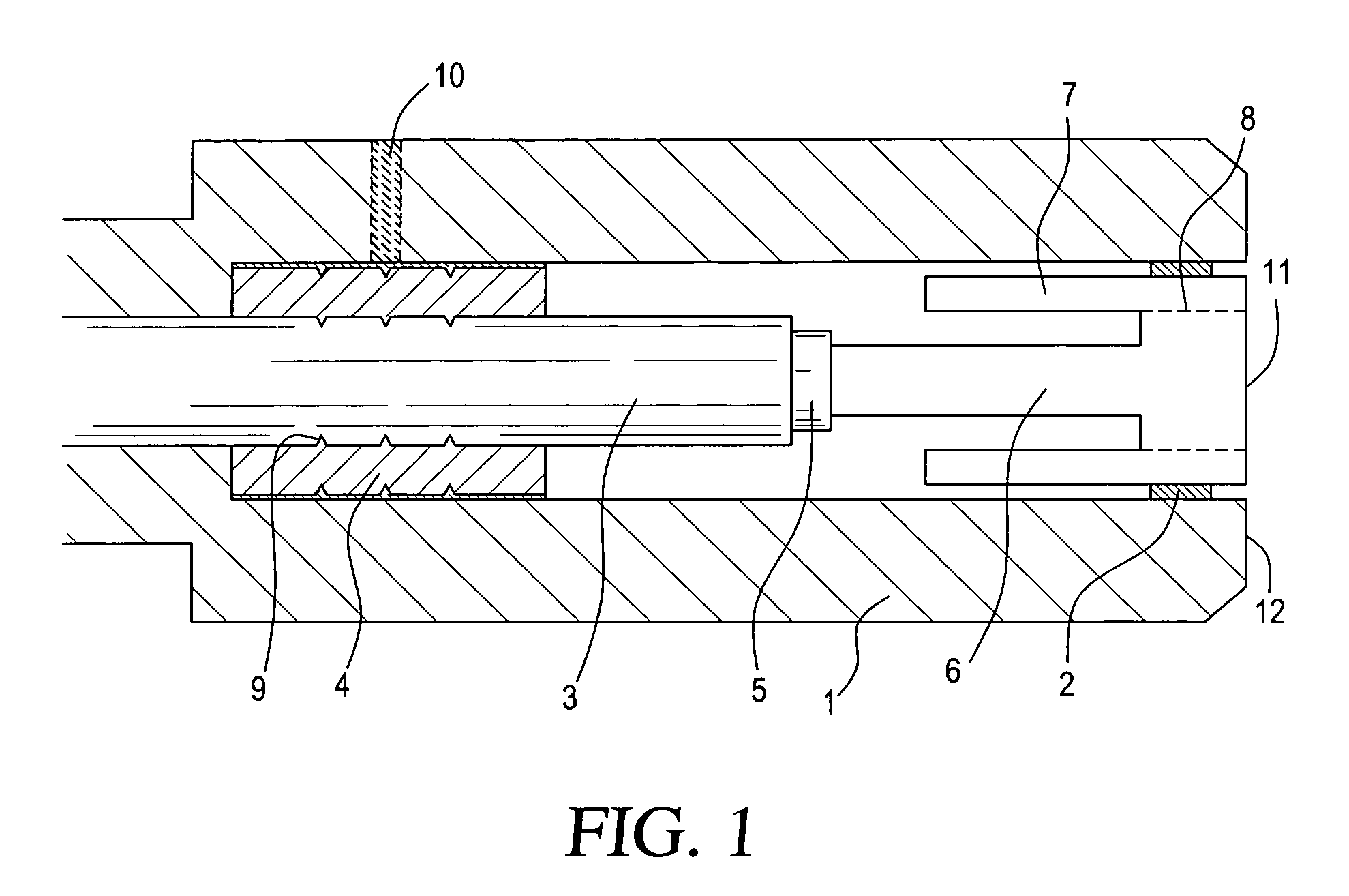
[0029]FIG. 1 illustrates a preferred embodiment of the invention including an optical fiber having a fiber core 6, a cladding layer 5, and a fiber buffer 3. The optical fiber may be made of any conventional fiber materials, including but not limited to glass or silica core materials, and glass, silica, or polymer cladding and buffer materials. A transparent ferrule 7 is fused or welded to the termination or coupling end of the fiber core in the region indicated by dashed line 8. The transparent ferrule may be made, by way of example and not limitation, of quartz or glass.

[0030]A crimp ferrule 4 is crimped onto the fiber buffer 6 at crimp region 9, but is not adhered or in contact with to the transparent ferrule 7. The crimp ferrule 4 may be used to hold the fiber during stripping of the cladding layer and welding or fusing of the transparent ferrule 7 to the fiber core 6, and as is conventional may be made of a malleable material such as metal. After completion of welding or fusing,...


PUM

PropertyMeasurementUnit
diameteraaaaaaaaaa
diameteraaaaaaaaaa
lengthaaaaaaaaaa

Abstract

A transparent ferrule is fused to an end of an optical fiber to increase the coupling area without altering the input numerical aperture of the fiber system. This is accomplished by controlling the length of the area at which the transparent ferrule is fused or welded. In addition, an extended ferrule portion is situated behind the fusion area and is separated from the fiber core such that light that fails to couple to the core is reflected from the inner diameter of the extended ferrule portion away from the fiber core, where it can be deflected or dissipated by a beam block or absorptive material. The transparent ferrule is formed from a plurality of relative thin wall ferrules that are successively fused from the side to form at the least the termination or coupling end of the transparent ferrule.

Description

[0001]This application claims the benefit of provisional application Nos. 60 / 876,521, filed Dec. 22, 2006, 60 / 960,568, filed Oct. 4, 2007, and 60 / 961,000, filed Oct. 24, 2007.BACKGROUND OF THE INVENTION[0002]1. Field of the Invention[0003]This invention generally relates to coupling of radiant energy from a radiant energy source to the conducting medium of a primary optical system, and in particular to a termination arrangement or connector for coupling laser energy to an optical fiber system, and to a method of manufacturing or assembling such a termination or connector.[0004]The invention allows for focusing a fixed spot into a smaller core fiber by utilizing refractive properties of a transparent ferrule surrounding the entrance surface of the fiber, while avoiding manufacturing and heat transfer problems associated with the fiber termination disclosed in U.S. Pat. No. 6,282,349 (Griffin).[0005]The invention may be used in a variety of laser deliver systems including, by way of e...

Claims


Application Information

Patent Timeline
Patent Type & Authority Patents(United States)
IPC IPC(8): G02B6/36G02B6/38
CPCG02B6/262G02B6/14
Inventor BROWN, JOE D.
Owner BROWN JOE D
Why Eureka
Try Eureka