
Hardware driven processor state storage prior to entering a low power mode

Active Publication Date: 2009-06-25
ARM LTD
View PDF5 Cites 40 Cited by
  • Summary
  • Abstract
  • Description
  • Claims
  • Application Information

AI Technical Summary

Benefits of technology

[0009]The present invention provides for the state of the processor to be automatically stored by hardware in response to a low power request thereby allowing the processor to be completely powered down in low power mode. The present invention makes use of existing hardware used to store data to memory during normal processing operations to perform this storage. This is efficient on processor area and also means that the hardware does not need to be specially designed for this state storage task at the implementation level. Furthermore, as the storage is under control of the processor, the state that is stored can be determined by the processor and can be limited to that that is required to restart the processor. Thus, an efficient selection of the relevant state can be made rather than storing the entire state of the processor. This along with the fact that storage is done using hardware improves the speed of the process.
[0011]Embodiments of the present invention can distinguish between standard reset signals and state restore reset signals by storing state reset indicator values in the power controller when state has been stored to memory before powering down. Thus, a power controller can power up the processor in response to a standard reset or can power it up and then signal to the processor to load state in response to a state restore reset enabling it to continue processing from the point at which it was powered down. Thus, embodiments of the present invention are able to process two different sorts of reset using hardware much of which is present in a conventional data processing apparatus.
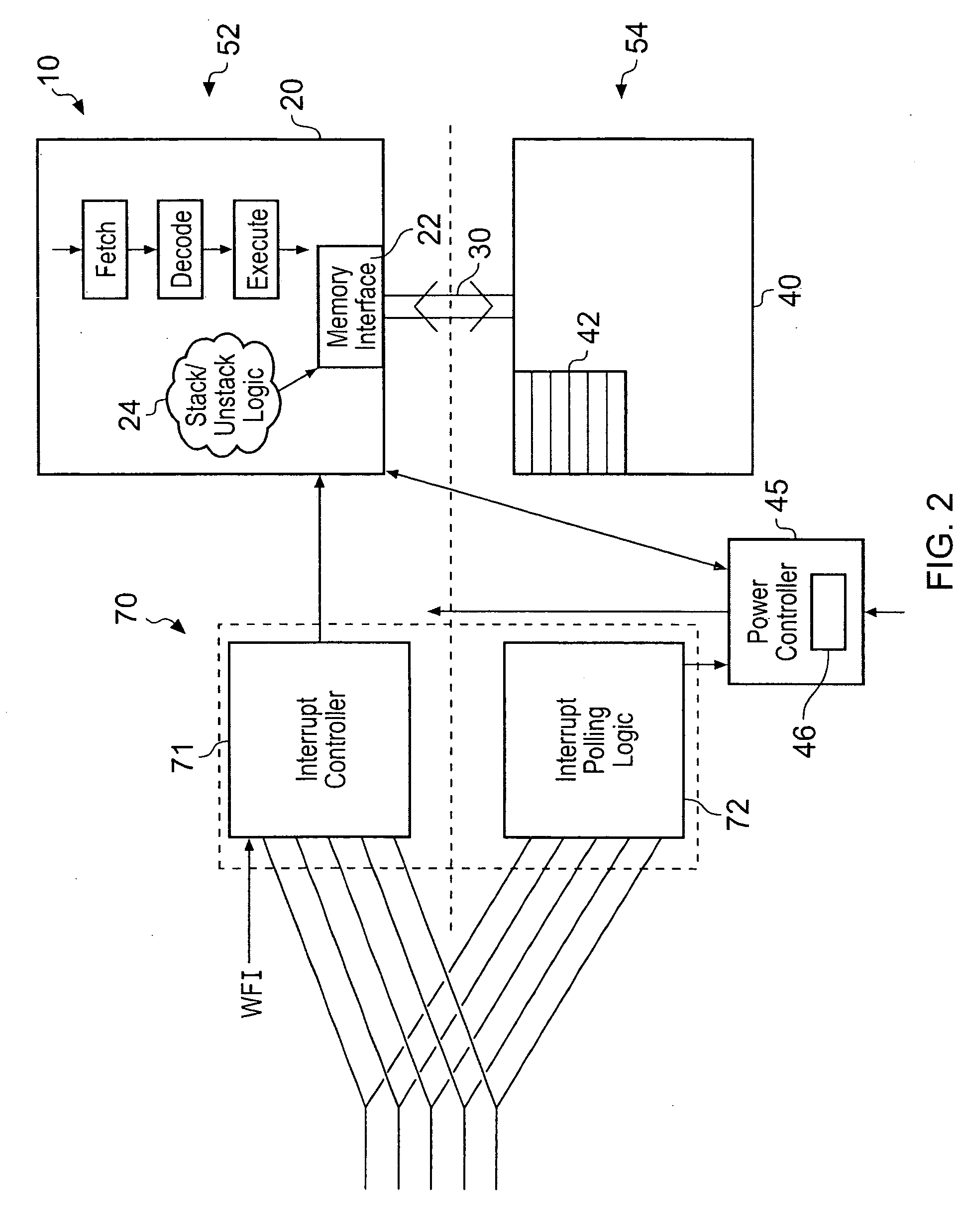
[0022]The interrupt controller can take a number of forms but in some embodiments it is formed in two parts, a first part being powered in the first power domain and the second part in the second power domain. Splitting the interrupt controller in this way allows for increased power savings when entering low power mode. It is only possible to split it in this way if the interrupt request monitoring circuit that monitors the power signals is in the second power domain.
[0024]In order to enable the interrupt monitoring circuitry to identify power up signals information is sent from the interrupt control circuitry prior to it being powered down. This information identifies which interrupts should trigger power ups. Sending information like this enables the complex part of the interrupt controller, that assesses the priority of the interrupts to be powered down in low power mode after it has sent the relevant priority information concerning interrupts to be received to the monitoring logic, this enables the monitoring logic to be simple logic and thus, not consume much power but still be able to identify interrupts that need to be serviced and in response to any received to enable power up.
[0026]It may be advantageous in response to the low power request to complete processing of pending instructions prior to powering down the processor. Handling low power requests in this manner enables the state that needs to be sent to be stored in the memory to be reduced compared to the state that would need to be sent if some instructions were still pending in the pipeline.

Problems solved by technology

Furthermore, as the storage is under control of the processor, the state that is stored can be determined by the processor and can be limited to that that is required to restart the processor.

Method used


Image

  • Hardware driven processor state storage prior to entering a low power mode
  • Hardware driven processor state storage prior to entering a low power mode
  • Hardware driven processor state storage prior to entering a low power mode

Examples


Embodiment Construction

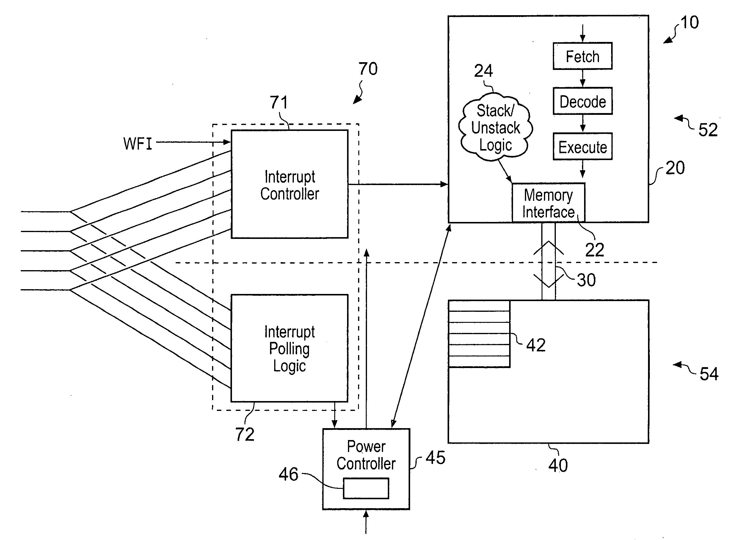
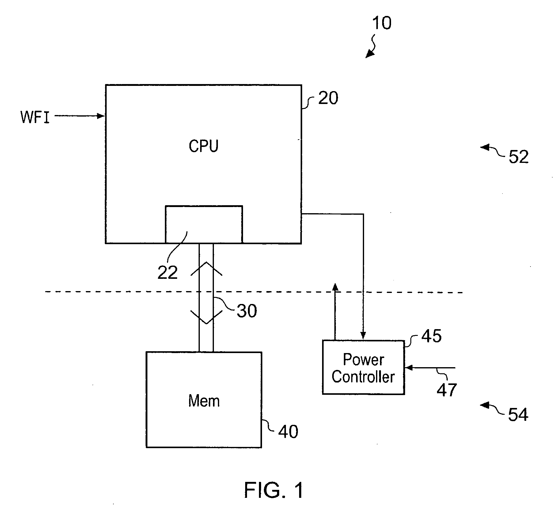
[0040]FIG. 1 shows a data processing apparatus 10 having a processor 20 with a memory interface 22 connected via a system bus 30 to a memory 40. The CPU processor is in a first power domain 52 while the memory 40 and a power controller 45 are in a second power domain 54.

[0041]Data processor 20 processes data according to instructions received and stores some of this processed data in memory 40. The storage and retrieval of data to memory 40 is controlled by memory interface logic 22. Thus, during normal data processing operations processor 20 processes data at least some of which it sends and / or receives from memory 40 via system bus 30 using memory interface logic 22.

[0042]The processor 20 is in a first power domain 52 the powering of which is controlled by power controller 45. The memory 40 and power controller 45 are in a second power domain 54. In order to save power when the processor 20 is not operational the power controller 45 is adapted to stop the clock to the processor 20...


PUM


Abstract

A data processing apparatus comprising: a processor for processing data, said processor comprising memory interface logic for controlling transfer of data to a memory, said processor being powered in a first power domain; a memory for storing data processed by said processor said memory being powered in a second power domain; a system bus coupled to said processor and said memory and operable to transfer data between said processor and said memory in response to memory transfer requests issued upon said system bus by said memory interface logic during normal processing operation of said processor and said memory; wherein said processor is responsive to a low power request indicating said data processing apparatus should enter a low power mode to: control transfer of state data indicating a current state of said processor to said memory via said system bus using said memory interface logic, said state data being sufficient data to restore said processor to an equivalent program state following exit from said low power mode; store said state data in said memory; and power down said first power domain.

Description

BACKGROUND OF THE INVENTION[0001]1. Field of the Invention[0002]The present invention relates to the field of data processing and in particular to the storing of a state of a processor prior to entering a low power mode in which the processor is powered down.[0003]2. Description of the Prior Art[0004]It is known to turn a clock off to a processor for periods when no work is required from it. This reduces power consumption, however there are still power losses due to leakage through the silicon. These power losses could be reduced by turning the power off to the core, but this has the drawback that state in the processor may be lost. It is important that when the low power mode is exited, the system should return to its previous state unaltered such that processing operations can continue smoothly and efficiently. It would be highly disadvantageous if information / state was lost during low power mode so as to require a full system reboot and initialisation upon restart. It is known to...

Claims


Application Information

Patent Timeline
IPC IPC(8): G06F1/32G06F1/26G06F13/24
CPCG06F1/3203Y02B60/1278G06F1/3287Y02B60/1282Y02D10/00
Inventor AXFORD, SIMONCRASKE, SIMON JOHN
Owner ARM LTD
Learn More