Air treatment device with reservoir refill

a technology of air treatment device and reservoir, which is applied in the direction of combustion-air/fuel-air treatment, steam generation using steam absorption, charge supports, etc., can solve the problems of increasing the cost of such devices, and increasing the difficulty of controlling the dispensing. , to achieve the effect of reducing the cost of such devices, and reducing the cost of production

Active Publication Date: 2010-01-26
SC JOHNSON & SON INC
View PDF19 Cites 33 Cited by
  • Summary
  • Abstract
  • Description
  • Claims
  • Application Information

AI Technical Summary

Benefits of technology

[0019]Alternatively the second well could also contain an air treatment chemical (e.g. a fragrance when the first well has an insecticide), a chemical that facilitates use of the first chemical (e.g. a synergist when the first well has an insecticide), or a material that can be usefully co-dispensed with a material in the first well but that must be kept separate from the first-well material prior to actual dispensing in order to avoid premature chemical or other interaction. Alternatively, first and second well materials may be selected to be simultaneously dispensed but for differing functionalities. An example of the latter would be the simultaneous dispensing of different insecticides, with a first being targeted at one insect and a second targeted at a second insect. For example, one might dispense transfluthrin to control flies and metofluthrin for superior mosquito control.
[0020]Any of these chemicals may be positioned in cartridge units, rather than just in wells directly. In any event, either the well or the cartridge can preferably be covered by a permeable (e.g. semi-permeable) membrane which controls volatization rates. These embodiments have an advantage that volatilization can carefully be controlled for two different chemicals.
[0023]It should be appreciated that the refills and devices of the present invention are inexpensive to produce, use heat extremely efficiently, and are capable of providing use-up cue information and / or multiple air treatments simultaneously. A use-up cue is any means for delivering a sensory cue that signals that the refill is exhausted or is nearing exhaustion and should be replaced. The inexpensive cost of such devices is particularly important in developing countries as cost of refills can be a significant barrier to the use of such devices.

Problems solved by technology

One problem with such devices is that the chemical to be dispensed, typically coated or impregnated on a porous substrate of some kind, usually rests against or near a heater.
This can create some inefficiencies.
For example, the portion of the material adjacent the heater can act as an insulator for the portion of the substrate which is releasing the active chemical, making control of the dispensing more difficult.
Another problem with such devices is that it may be difficult to determine when such a device is used up.
Yet another problem relates to a lack of flexibility where multiple chemicals are to be dispensed which are optimally dispensed under different heating conditions.

Method used


Image

  • Air treatment device with reservoir refill
  • Air treatment device with reservoir refill
  • Air treatment device with reservoir refill

Examples


Embodiment Construction

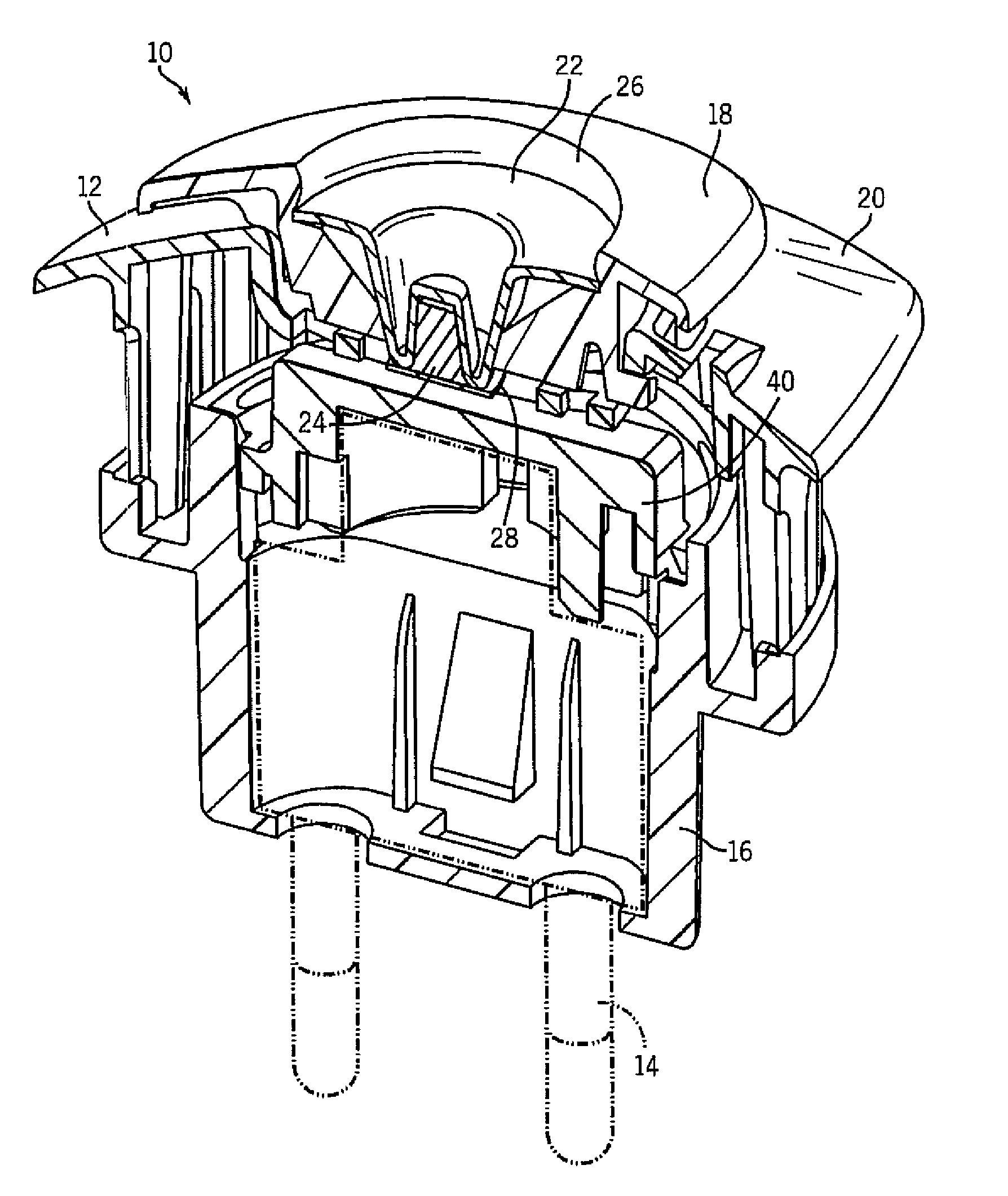
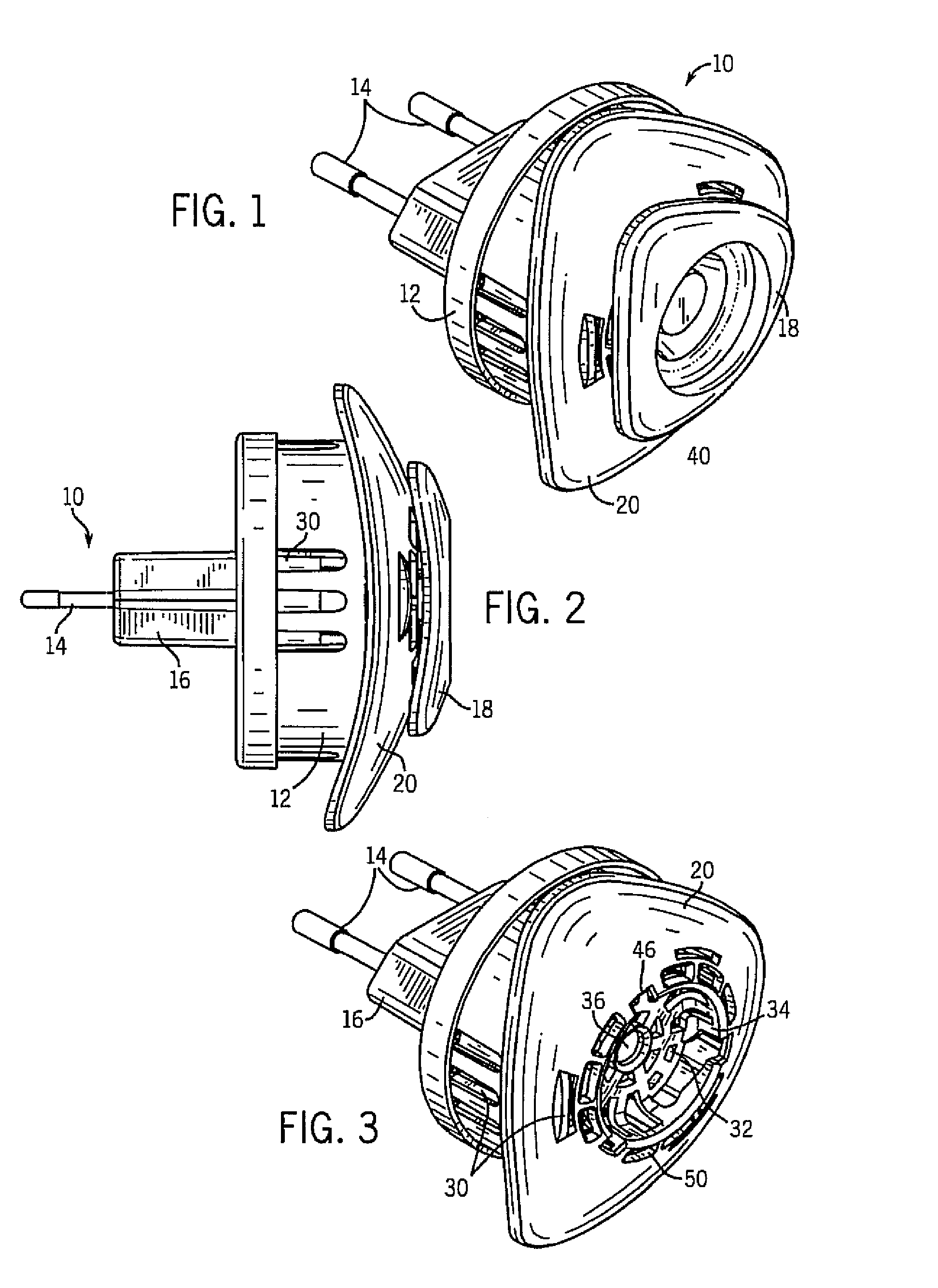
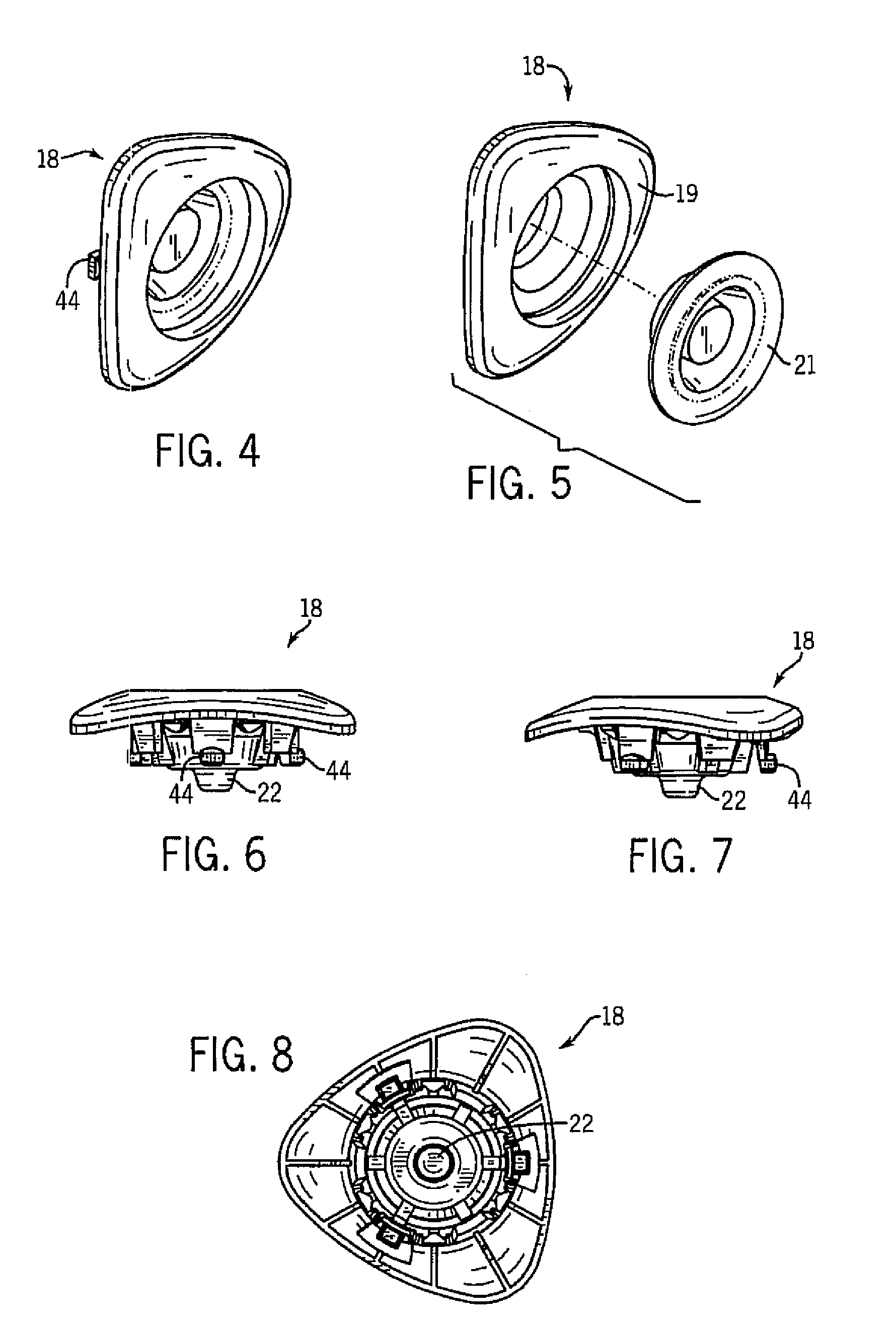
[0045]Referring first to FIG. 1, an air treatment device 10 is shown having a housing 12 with electrical prongs 14 at a rear end 16 and a removable refill 18 attached at an opposing forward end 20. The device 10 is most preferably plugged into an electric socket on a vertical wall. Hence, the directional terms in this patent are used with that type of installation in mind. However, appropriate electric sockets on horizontal or other surfaces may also be used to provide power. Thus, the terms such as “front”, “rear”, “upper”, “lower”, and “side” should be interpreted in an analogous manner when the devices are used for that type of installation.

[0046]The prongs 14 shown in the figures are merely for purposes of example. Cylindrical prongs of this type are suitable for linking to electric power in some countries. However, in other countries blade prongs, or mixtures of blades, cylinders and other shaped prong elements will be used to supply the linkage to the available power (as is we...


PUM

PropertyMeasurementUnit
weight percentaaaaaaaaaa
transparentaaaaaaaaaa
volatileaaaaaaaaaa

Abstract

Disclosed are devices for dispensing air treatment chemicals, and refill units for use therewith. Some of these devices have a well facing the heater and a transparent wall to view the use up of the air treatment chemical. Other of these devices have a refill with wells positioned in opposing directions.

Description

CROSS-REFERENCE TO RELATED APPLICATIONS[0001]Not applicableSTATEMENT REGARDING FEDERALLY SPONSORED RESEARCH / DEVELOPMENT[0002]Not applicable.BACKGROUND OF THE INVENTION[0003]The present invention relates to devices that dispense a volatile air treatment chemical by heating a chemical housed in a reservoir. It also relates to improved refills for use with such devices.[0004]The prior art is replete with attempts to efficiently dispense air treatment chemicals such as insect control agents (insecticides, insect repellents, insect growth regulators, attractants, synergists, etc.), fragrances and deodorizers. See e.g. U.S. Pat. No. 6,551,560. The disclosure of this patent, and of all other patents referred to herein, are incorporated by reference as if fully set forth herein.[0005]Conventional devices typically dispense a volatile air treatment chemical by heating a substrate on one side, thereby causing dispensing in an opposed direction. The heating source is typically an electrical he...

Claims


Application Information

Patent Timeline
Patent Type & Authority Patents(United States)
IPC IPC(8): A61L9/00A01G13/06A01M13/00A21B1/00A24F25/00A62B7/08B01D47/00B65G59/00B65H1/00F27D11/00H05B3/06
CPCA01M1/2077A61L9/12A61L9/03
Inventor ADAIR, JOEL E.DAVIS, BRIAN T.ANANTH, GOPAL P.MATHER, DAVID P.
Owner SC JOHNSON & SON INC
Why Eureka
Try Eureka