Protective electrical outlet cover having integrated positive locking mechanism

a technology of positive locking mechanism and protective electrical outlet cover, which is applied in the direction of electrical apparatus casing/cabinet/drawer, coupling device connection, instruments, etc., can solve the problems of more complicated devices, high cost of covers, and lack of positive locking feature of safety devices, so as to maintain the safety of the utility.

Inactive Publication Date: 2010-01-26
SOCKET LOCKITS
View PDF18 Cites 81 Cited by
  • Summary
  • Abstract
  • Description
  • Claims
  • Application Information

AI Technical Summary

Benefits of technology

[0012]The present invention is directed to an outlet protection device with a cover for protecting an electrical socket that is inexpensive to manufacture, easy to use, and which provides a positive locking mechanism, requiring force to be applied simultaneously in at least two directions for removal.
[0013]In one embodiment of the invention, the cover has at least one prong for engaging the opening of the electrical socket and a reverse tongue defined within the prong having a barb disposed thereon for positively engaging the rear surface of either rectangular opening of the socket. Unlike other safety covers, the flexible tongue defined in the prong carrying the barb acts as a catch on the back of the socket opening. After engaging the socket, any attempt to remove the cover without displacing the barbed tongue is averted by the barb, which engages with more strength against the back of the socket as it is pulled from the outlet, thereby acting as a self-reinforced locking mechanism.
[0017]Removal of the cover requires the tongue to be deflected at the same time a pulling force is exerted on the cover. This dual activation makes it significantly more complicated for children to figure out the release process, making it more likely that the devices will not be removed the children.

Problems solved by technology

These types of covers tend to be expensive since they are manufactured as a series of assembled components and require removal and discard of the existing outlet plate.
Further, these types of safety devices do not have a positive locking feature.
Because these types of cover plugs are easy to remove, and lack a positive locking feature, they have traditionally been manufactured in material and shapes that do not suggest to children that they are objects of attention.
Other designs have improved on this idea and have provided more complicated devices.
Both of these designs, however, suffer from the disadvantage of being relatively complicated and comprise multiple parts, requiring assembly, making them relatively expensive to manufacture.
In addition, it is desirable to have an outlet protection device that requires force to be applied simultaneously in two different directions to increase the complexity of removal of the device from the outlet.

Method used


Image

  • Protective electrical outlet cover having integrated positive locking mechanism
  • Protective electrical outlet cover having integrated positive locking mechanism
  • Protective electrical outlet cover having integrated positive locking mechanism

Examples


first embodiment

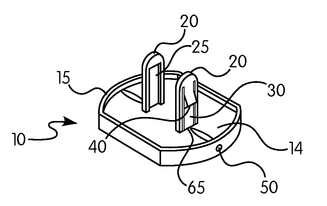
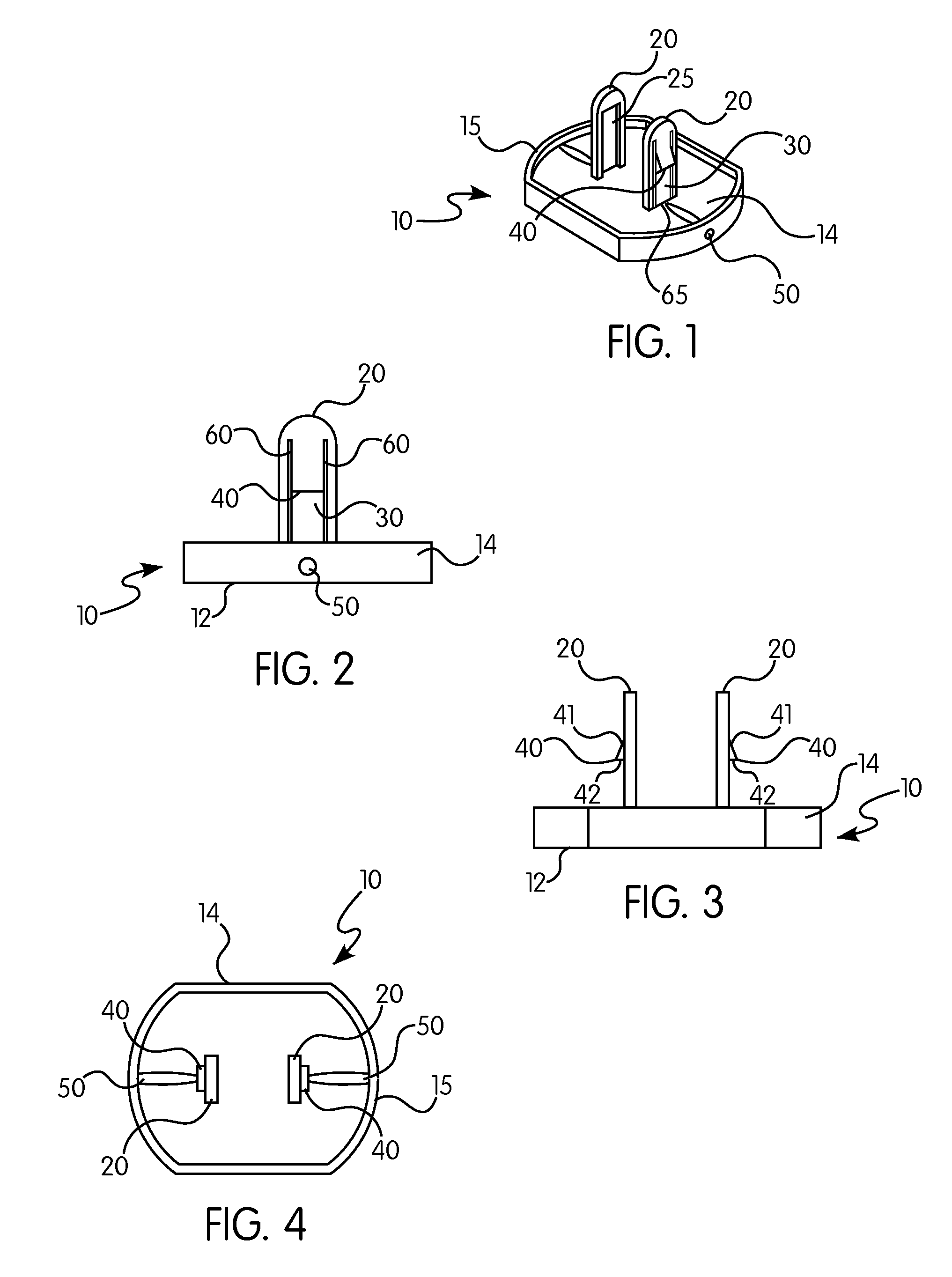
[0038]FIGS. 1-4 show the protective cover 10 of the present invention. Protective cover 10 has main body 14 having front face 12 and defining rim 15 around the rear perimeter thereof. Main body 14 has two prongs 20 extending from the rear surface thereof, each of prongs 20 is a generally rectangular shape structure defining a reverse tongue 30 with barbs 40. Reverse tongues 30 are relieved from prongs 20 on either side with slits 60 and on the lower end thereof with slit 65. Tongue 30 is also relieved on the inside surface 25, having a thinner cross sectional area than the remainder of prong 20, to allow barbs 40 to deflect within the width of prong 20 while being inserted into an electrical outlet.

[0039]Ramped surfaces 41 on one side of barbs 40 cause the deflection of tongue 30 during insertion of the device, and allows barbs 40 to fit within the width of the rectangular openings on the outlet. When prongs 20 have been fully inserted into a typical electrical outlet, tongues 40 wi...

second embodiment

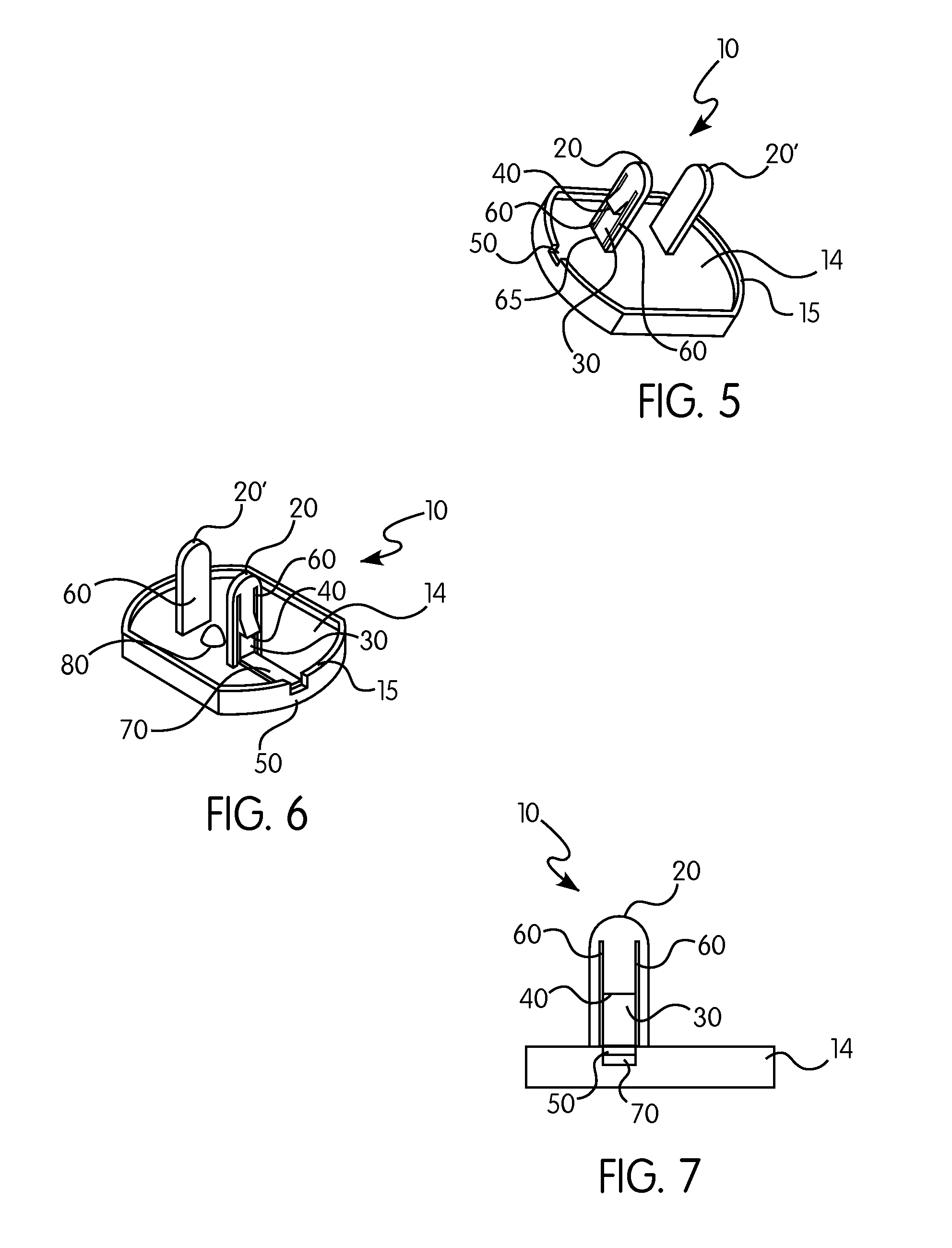
[0042]FIGS. 6-8 show the invention. In many aspects, this embodiment is essentially identical to the embodiment shown in FIG. 1. The main difference is the presence of tab 70 that protrudes through or is accessible through opening 50 defined in rim 15. Tab 70 may be pressed from the outside of protective cover 10 to disengage barb 40 from the rear surface of the outlet. Tab 70 may protrude slightly through rim 15, or may be slightly recessed within the rim. Note that, for tab 70 to work properly, tab 70 must be able to slide freely back and forth, and must therefore remain offset from the outlet. Post 80, located between prongs 20 and 20′ serves to keep the body of device 10 from pressing tab 70 into the surface of the outlet.

[0043]As with the embodiments shown in FIGS. 1-5, all variations as discussed above with respect to the embodiment of FIGS. 1-5 are contemplated to be applicable to this embodiment as well.

third embodiment

[0044]FIGS. 9-10 shows the invention in which protective cover 10 is configured with barbs 40 having a slightly different shape than those of previous embodiments. In this embodiment, rim 15 has no openings, as tongues 40 need not be deflected using external means to effect removal of the device. Instead, in this embodiment, barbs 40 have two ramped surfaces 41 and 42, and tongues 30 are only relieved from prongs 20 on their sides by slots 60. Additional slot 65 is not present on the bottom of tongues 30, as with other embodiments. To remove protective cover 10 having this design, additional pulling force is required, as tongue 30 will be more difficult to deflect. Ramped edge 42 defined on barb 40 will deflect tongue 30 inwardly until barb 40 is released from the rear surface of the outlet.

[0045]Variations on this embodiment (not shown) are similar to those for the embodiments shown in FIGS. 1-8, including having only one prong 20 having a tongue 30 define therein and one solid pro...


PUM


Abstract

A safety device for electrical outlets includes a body having prongs rigidly attached to the body which can be inserted into the openings of a standard electrical outlet, wherein one or more of the prongs define a spring-biased portion defining a barb for engaging the rear surface of the outlet once the device is fully inserted therein.

Description

RELATED APPLICATIONS[0001]This application claims the benefit of U.S. Provisional Application Ser. No. 60 / 937,959, filed Jun. 29, 2007, entitled “Electrical Outlet Protection Device”.BACKGROUND OF THE INVENTION[0002]It is generally well known in the art to cover electrical outlets with protective outlet covers to prevent unwanted tampering, especially by babies and young children, and, for outdoor outlets, for purposes of weatherproofing the outlet.[0003]The outdoor cover designs include box shaped structures surrounding the outlet or cover plate implementations, which are offered with a variety of miniature spring-loaded doors covering the individual sockets. The miniature doors are provided so that they slide or pivot out of the way to accommodate an electrical cord to be plugged into the outlet.[0004]The same concept of a cover plate has been extended into the interior of the home as a child safety device. Installation of the device, most often requires the removal of the existin...

Claims


Application Information

Patent Timeline
Patent Type & Authority Patents(United States)
IPC IPC(8): H02G3/14
CPCH02G3/14H01R13/447H01R13/443
Inventor WHITE, PATRICK M.
Owner SOCKET LOCKITS
Why Eureka
Try Eureka