Graphical user interface for emergency apparatus and method for operating same

a technology of emergency apparatus and user interface, applied in the field of network and communication system, can solve the problems of difficult recovery or finding of stationary transceivers, large size of stationary transceivers, and large amount of power, and achieve the effects of time-consuming and laborious, and reducing the cost of operation

Inactive Publication Date: 2010-01-26
SCOTT TECH INC
View PDF105 Cites 68 Cited by
  • Summary
  • Abstract
  • Description
  • Claims
  • Application Information

AI Technical Summary

Benefits of technology

[0006]It will be appreciated that some configurations of the present invention provide a small apparatus that an incident command officer on the scene may use to obtain information needed to efficiently perform his tasks and to obtain this information in a useful format. In addition, in some configurations, sensor monitoring systems used by emergency services personnel that are provided with logging systems can have their log files downloaded and archived without requiring a physical connection between the sensor monitoring system and the archiving system.

Problems solved by technology

However, stationary transceivers are large, heavy and require large amounts of power.
Additionally, stationary transceivers, once deployed, are difficult to recover or find after the emergency is over, because stationary transceivers are typically lost or destroyed by the firefighters, emergency, or military personnel on the scene.
Further, deployment of such stationary transceivers is time consuming and is often not practical under typical emergency circumstances.
The location of the central base station may not be convenient for an incident command officer to obtain all of the information needed to efficiently perform his tasks or to obtain this information in a useful format.
Known archiving systems are inconvenient in that they require a physical connection between the sensor monitoring system and the archiving system.

Method used


Image

  • Graphical user interface for emergency apparatus and method for operating same
  • Graphical user interface for emergency apparatus and method for operating same
  • Graphical user interface for emergency apparatus and method for operating same

Examples


Embodiment Construction

[0025]As used herein, an element or step recited in the singular and proceeded with the word “a” or “an” should be understood as not excluding plural said elements or steps, unless such exclusion is explicitly stated. Furthermore, references to “one embodiment” of the present invention are not intended to be interpreted as excluding the existence of additional embodiments that also incorporate the recited features. Moreover, unless explicitly stated to the contrary, embodiments “comprising” or “having” an element or a plurality of elements having a particular property may include additional such elements not having that property.

[0026]Referring now to the drawings, in which like numerals represent like components throughout the several views, embodiments of the present invention are next described. The following description of the embodiment(s) is merely exemplary in nature and is in no way intended to limit the invention, its application, or uses.

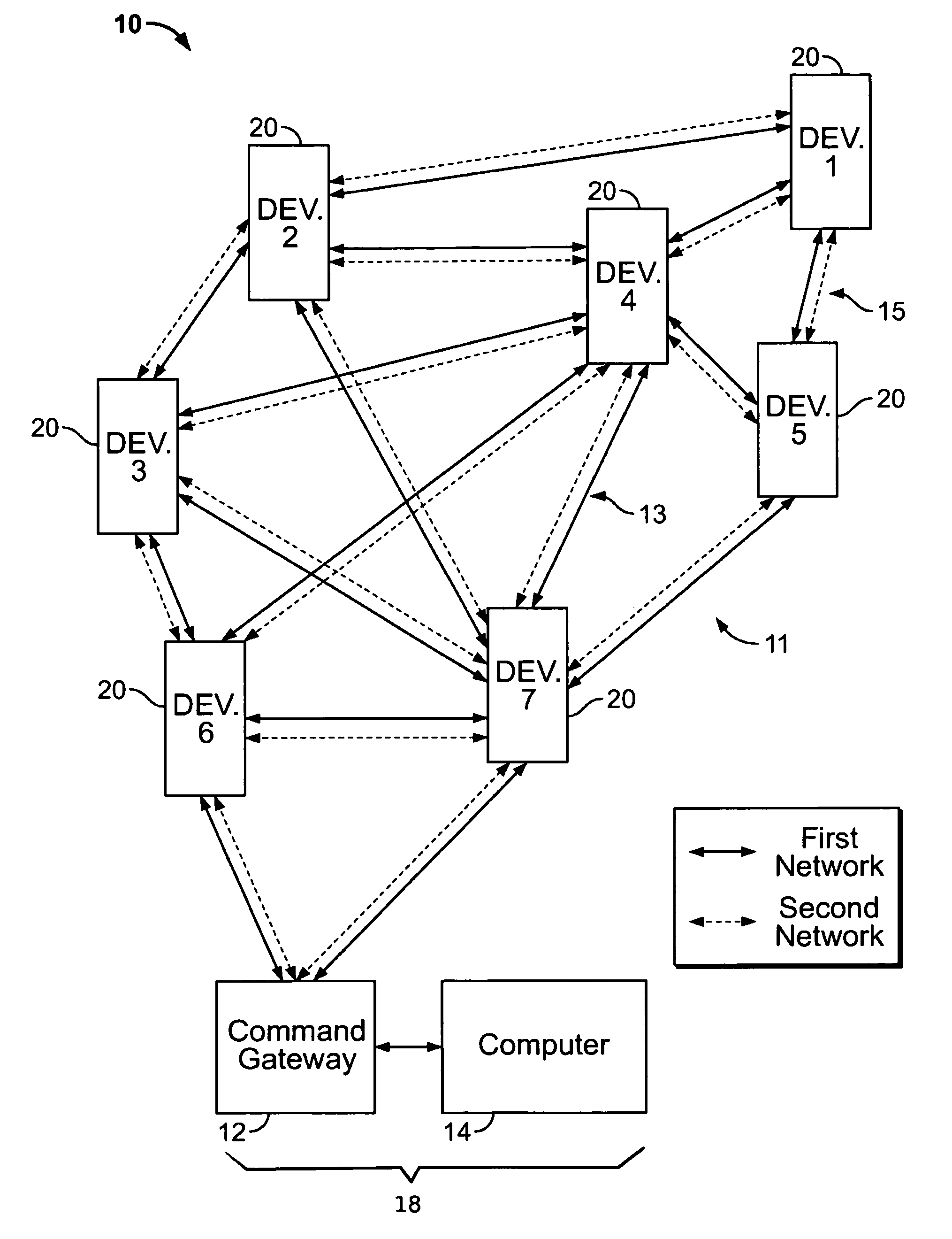
[0027]FIG. 1 is a block diagram of ...


PUM


Abstract

A communications system for emergency services personnel can include portable devices to be carried by emergency services personnel while at an emergency site. The portable devices each may have at least a first transceiver configured to communicate over a first network and the portable devices are configured to communicate with one another. The system may also include a portable gateway apparatus. The portable gateway apparatus may have a portable computer having a graphical user interface (GUI) and a PCMCIA or smaller card that itself includes at least a first radio. The first radio is configured to communicate over the first network to obtain status information from the portable devices carried by the emergency services personnel. The GUI is configured to communicate with the PCMCIA card to display a node map indicating communication links between the portable devices carried by the emergency services personnel.

Description

BACKGROUND OF THE INVENTION[0001]The present invention relates generally to a network and communication system used by emergency personnel and more particularly to a network and communication system for use therewith.[0002]Firefighter or other first response personnel systems with combination location / tracking, electronics and sensor monitoring indoors / outdoors are very helpful in emergencies. It is very desirable for an incident commander to be in contact with his / her personnel and to monitor their location, the electronic sensors and electromechanical equipment they carry with tracking capabilities at the scene of an emergency. Conventional systems have relied on personnel arriving at the scene of an emergency and deploying temporary stationary transceivers, such as beacons, repeaters and antennas inside and outside a building or structure in order to relay information to a central base station. The deployment of these stationary transceivers is necessary to relay information to / f...

Claims


Application Information

Patent Timeline
Patent Type & Authority Patents(United States)
IPC IPC(8): G08B21/00
CPCG01S13/878G08B21/02G01S11/06
Inventor PARKULO, CRAIG MICHAELMARSHALL, JULIE
Owner SCOTT TECH INC
Why Eureka
Try Eureka