
System and user interface supporting task schedule configuration

a task schedule and user interface technology, applied in the field of work flow management systems, can solve the problems of affecting the development and operation of work flow engines, and not providing the functionality of generic work flow engines for such customers

Active Publication Date: 2010-01-26
CERNER INNOVATION
View PDF33 Cites 17 Cited by
  • Summary
  • Abstract
  • Description
  • Claims
  • Application Information

AI Technical Summary

Benefits of technology

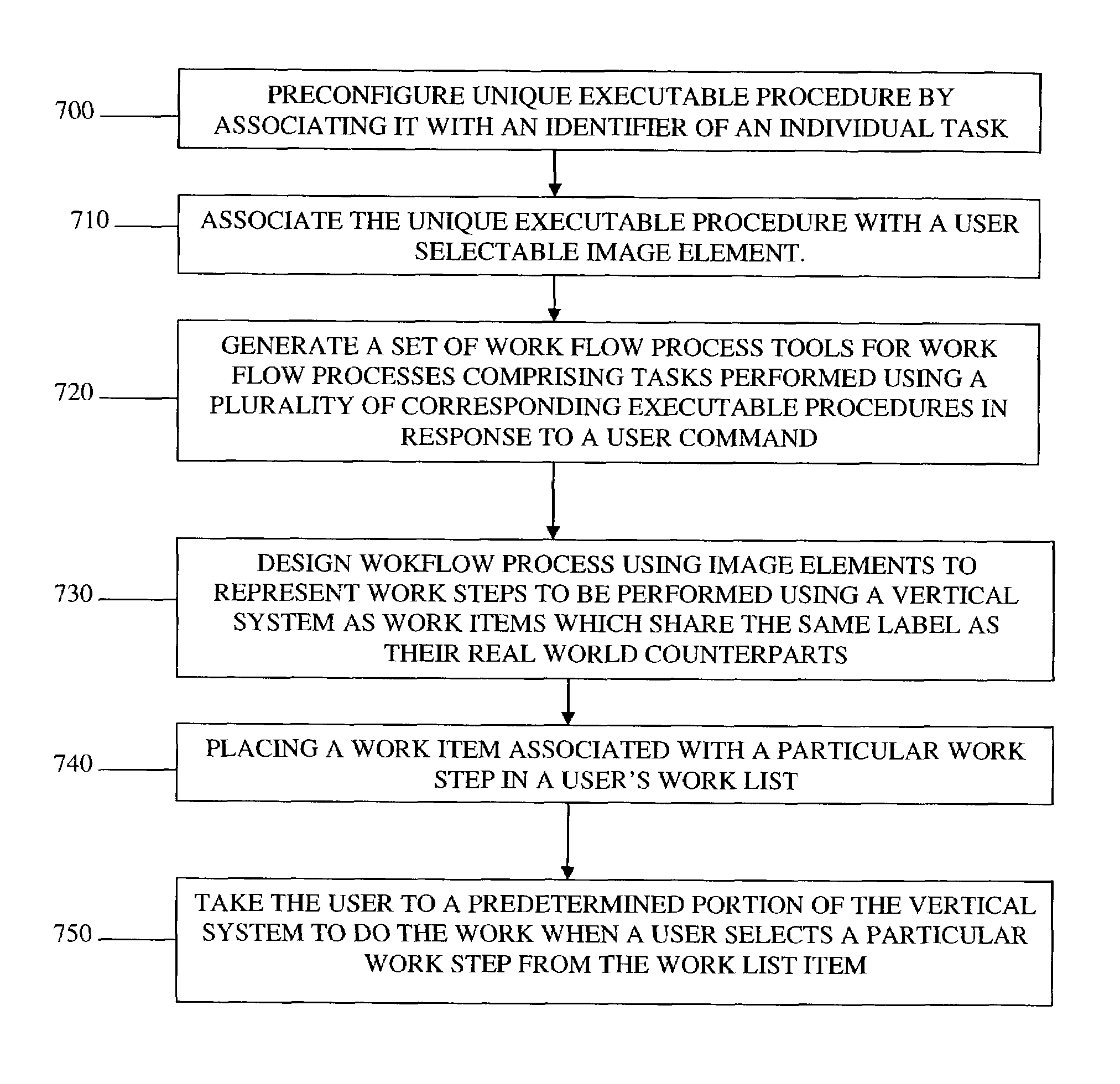
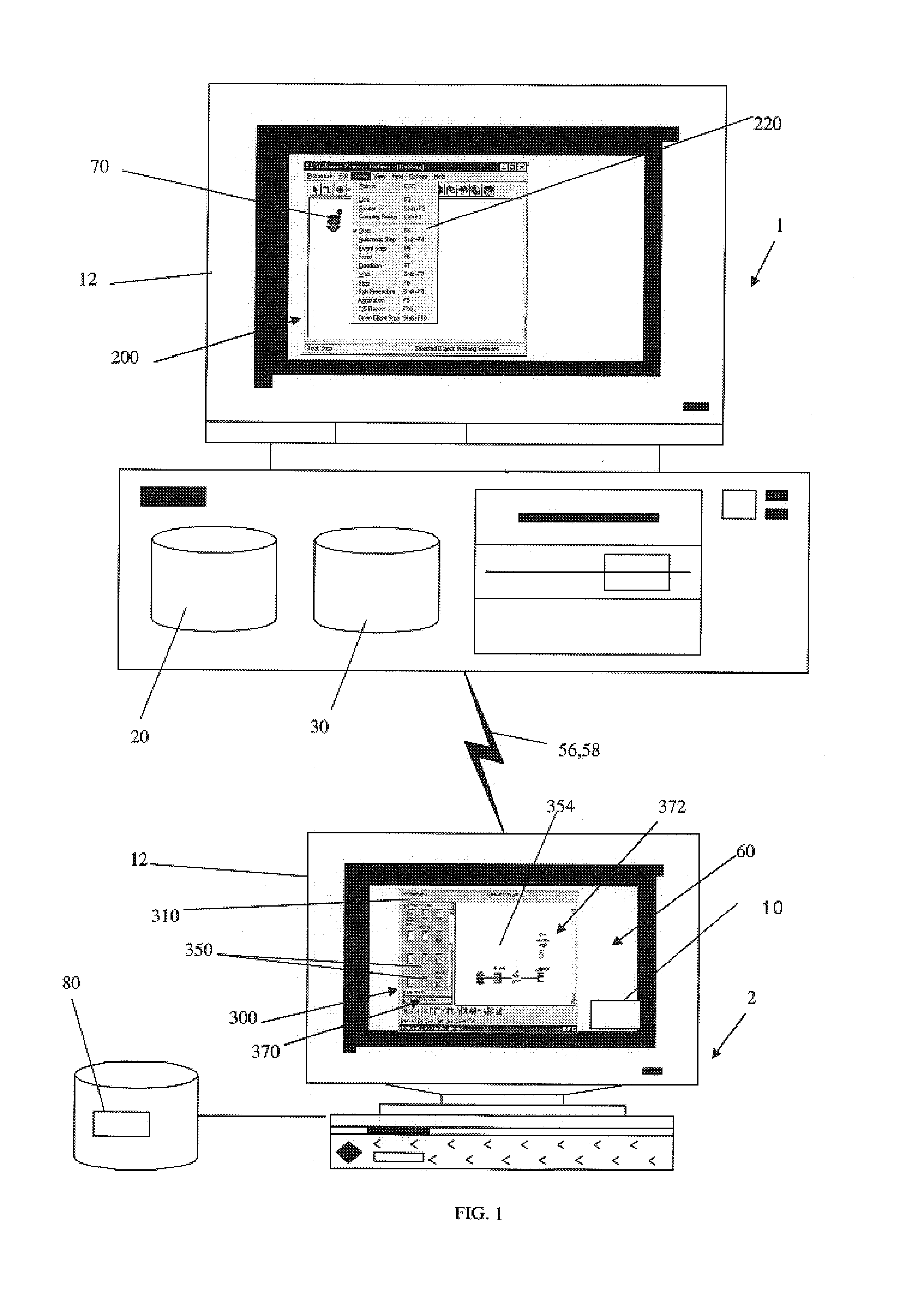
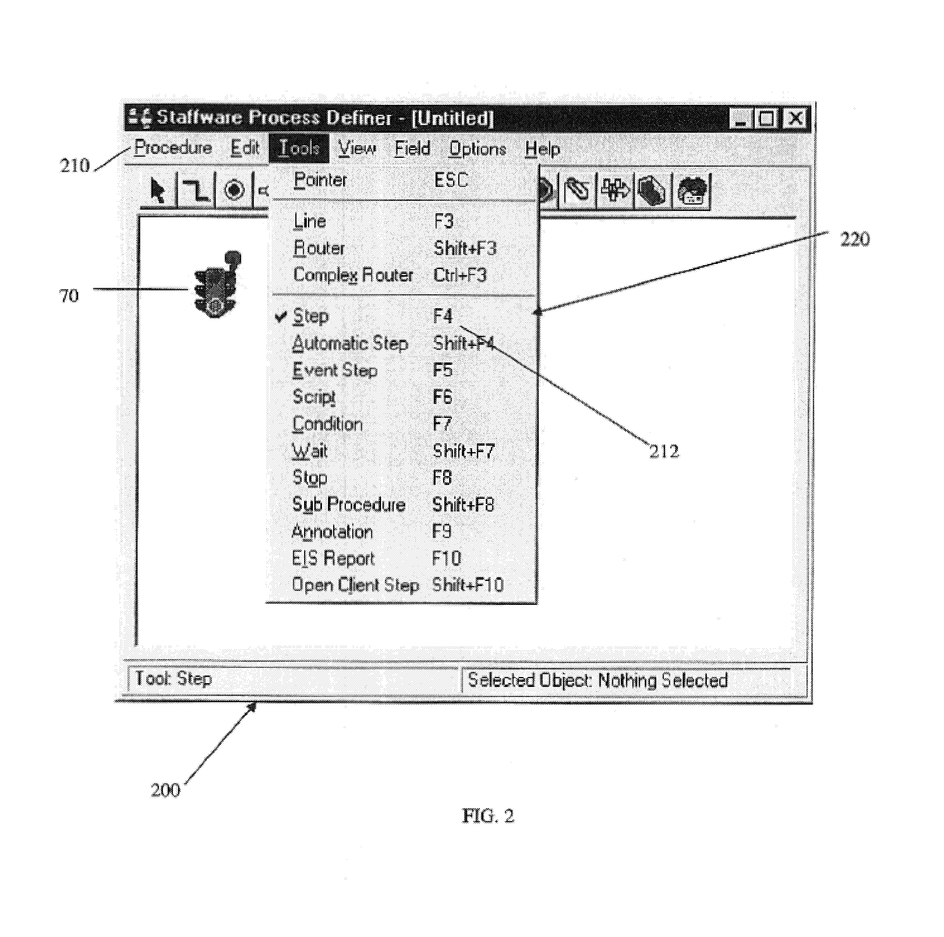
[0008]As will be understood, a work flow comprises one or more tasks to be accomplished. In an embodiment of the present invention, a user interface that supports user creation of a work flow may be provided by selecting, in response to a user command, a user selectable displayed image element associated with a pre-configured executable procedure to associate the selected displayed image element with a particular task of a work flow. In a preferred embodiment, the particular task comprises a corresponding executable procedure that

Problems solved by technology

However, those customers who require such work flow often have to perform substantial work flow configuration processes, including configuring process interface specifications for individual work steps.
Generic work flow engine vendors do not provide requisite functionality for such customers as the generic work flow engine vendors typically do not have knowledge of the work flow relevant capabilities of specific software systems into which their work flow product will be embedded.
Additionally, although work flow engines may be well suited for direct configuration and implementation by end users, work flow engines are not well suited for secondary distribution, e.g. embedding in a second software application environment, in part because they place the entire burden of defining the interaction with the second software application system upon a work flow process designer.

Method used


Image

  • System and user interface supporting task schedule configuration
  • System and user interface supporting task schedule configuration
  • System and user interface supporting task schedule configuration

Examples


Embodiment Construction

[0025]In general, throughout this description, if an item is described as implemented in software, it can equally well be implemented as hardware. Further, as used herein, “end user” and “customer” are understood to comprise a individual user, a group or category of users, a role or characteristic of one or more users, a particular device or system such as a medical device or system, and the like, or a combination thereof.

[0026]As used herein, “communication link” comprises data communications pathways, both logical and physical, e.g. interprocess messaging, interprocessor data transmissions, and local and wide area data communications links. “File structure” comprises a data file contained in a transient or permanent storage medium such as RAM or a computer hard drive, a folder or other director structure, a directory, a database, and the like, or a combination thereof, as these terms will be familiar to those of ordinary skill in the computer arts.

[0027]Additionally, “executable p...


PUM


Abstract

In an embodiment of the present inventions, a work flow process may be generated by decomposing functions of a clinical information system into discrete tasks including an individual task associated with a first pre-configured executable procedure for implementing the individual task and associating a user selectable image element with the pre-configured first executable procedure used in implementing the individual task. In a currently envisioned embodiment, integratable work flow processes according to the present invention may be provided to a vertical application system.

Description

PRIORITY[0001]This application claims priority through U.S. Provisional Application No. 60 / 316,603 filed Aug. 31, 2001 for “A System And User Interface For Supporting Task Schedule Configuration.”BACKGROUND OF THE INVENTION[0002]The present invention relates to work flow management systems in general, and more specifically to work flow engines that may be embedded within a more comprehensive software application, e.g. a healthcare software application system.[0003]A vendor (e.g., a systems integrator, sometimes referred to hereinafter as an “OEM”) of software applications amenable to work flow functionality typically needs to supply its end user customer with a means of configuring the customer's work flow supported by the OEM's software system. However, those customers who require such work flow often have to perform substantial work flow configuration processes, including configuring process interface specifications for individual work steps. Thus, an end user customer will also b...

Claims


Application Information

Patent Timeline
IPC IPC(8): G06F15/00G06F9/45G06F9/40G06F9/44G06Q50/00
CPCG06F8/34G06Q10/06G06Q10/0633G06Q10/10G06Q10/1095G06Q50/00G06Q50/22G16H40/20
Inventor BRANDT, SAMUEL I.DEHAAN, JAN
Owner CERNER INNOVATION
Learn More