Rotating therapeutic bed

a therapeutic bed and rotating technology, applied in the field of rotating therapeutic beds, can solve the problems of many people who make it to survive traffic accidents partially or fully lose their body motility control, and accidents that take pla

Inactive Publication Date: 2010-02-02
CIATEQ A C
View PDF17 Cites 80 Cited by
  • Summary
  • Abstract
  • Description
  • Claims
  • Application Information

AI Technical Summary

Benefits of technology

[0029]Considering the defects of the previous art, it is an object of the present invention to provide a rotating therapeutic bed having an extremely simple, practical, and economical construction and being also highly effective to change the position of a patient from being laying on his back to being laying face down by means of turning him 180°, such rotationally movement being performed in a very easy fashion but, above all, with the greatest safety to prevent the patient from suffering injuries.
[0033]Yet another object of the present invention is to provide a rotating therapeutic bed including rotation-blocking means preventing the bed from rotating when it is partially disassembled.
[0034]Yet another object of the present invention is to provide a rotating therapeutic bed whose main components may be easily removed.
[0035]Yet another object of the present invention is to provide a rotating therapeutic bed whose base allows the handling of the bed throughout narrow corridors.
[0038]Yet another object of the present invention is to provide a rotating therapeutic bed on which, when the patient is laying face down, has a free visual field to read books or watch television screens.
[0039]Yet another object of the present invention is to provide a rotating therapeutic bed designed to connect the patient to means and lines allowing to carry out the patient's cervical traction operation or allowing to provide saline solution to the patient, without those means or lines interfering with rotating the patient.

Problems solved by technology

In modern society, there is a series of accidents that takes place often.
In developed societies, accidents related to car traffic are one of the main causes of death.
Likewise, many people who make it to survive those traffic accidents partially or fully lose their body motility control due to the injuries resulting from the abovementioned traffic events.
In addition to accidents, whether they are car traffic ones or not, there are other causes resulting in the loss of voluntarily moving some part of one's body.
On the other hand, permanent paralysis results from extended injury in nerve cells or a nerve root, where nerve cells being seriously injured cannot regenerate.
The immovability of quadriplegic patients makes them to be most of the time laying on a bed and they are thus at risk of developing eschars and sores on their skin, since their immovability prevents them from moving their body and place them in a different position as often as normal people may do so.
This bed has a quite complicated design, since one of its objects is to be used in the treatment of patients having respiratory problems, being thus only used in hospitals and being operated exclusively by qualified personnel, which is a disadvantage when the bed is used for quadriplegic patients who, most of the times, are at their own home and are directly taken after by their relatives.
Furthermore, beds must not have protuberances or projections that may prove dangerous when the patient position is changed.
Likewise, the operation of the previously depicted bed may represent a complex task for one person alone, since it is necessary to make a considerable effort to place on the patient the cushions which support him in a position in which he lies face down and which are adjusted and secured by using strings to rotate then the rings allowing to perform the 180° rotation.
Furthermore, the safety of the patient laying face down may be reduced in this bed if the strings had not been properly stretched.
Another disadvantage that may be found in the bed depicted in the International Application No.
In particular, with such bed there is only access to the patient's back when he is in such a position, since the support platform makes the access to the patient difficult, since it is securely fixed on the rings.
PCT / IE99 / 00049, it can be mentioned that such a bed is to be used mainly in hospitals and, furthermore, it continues to show problems with respect to the limited access to patients when they are laying face down.
However, as any electromagnetic device, there is the risk for failures in sensors, which would result in a full failure of the safety system.
As it may be seen, the beds depicted in the three abovementioned documents share a very similar structure, which is complex and bulky, mainly because the base with wheels is basically formed by a horizontal rectangular frame provided with various elements in order to provide the “Trendeleburg” position and provide support to the guide rings and, furthermore, the rings mounted at the bed head and foot are also very bulky.
However, the beds from the previous art do not allow this possibility.
Another important issue in these beds is that the lowest possible force is needed to change the patient position by a 180° turn, while in the beds from the previous art such a turn was achieved by means of electric motors.
Likewise, another disadvantage of the beds from the previous art is that, since they include electric or electromagnetic components, they cannot be in contact with water and thus patients need to be relocated in other devices for bath.
As it may also be seen, the beds from the previous art, due to their design and use in hospitals, are considerably expensive and they are thus not affordable by families of developing countries, such as Mexico, where an important percentage of the population has low income and quadriplegic relatives.

Method used


Image

  • Rotating therapeutic bed
  • Rotating therapeutic bed
  • Rotating therapeutic bed

Examples


Embodiment Construction

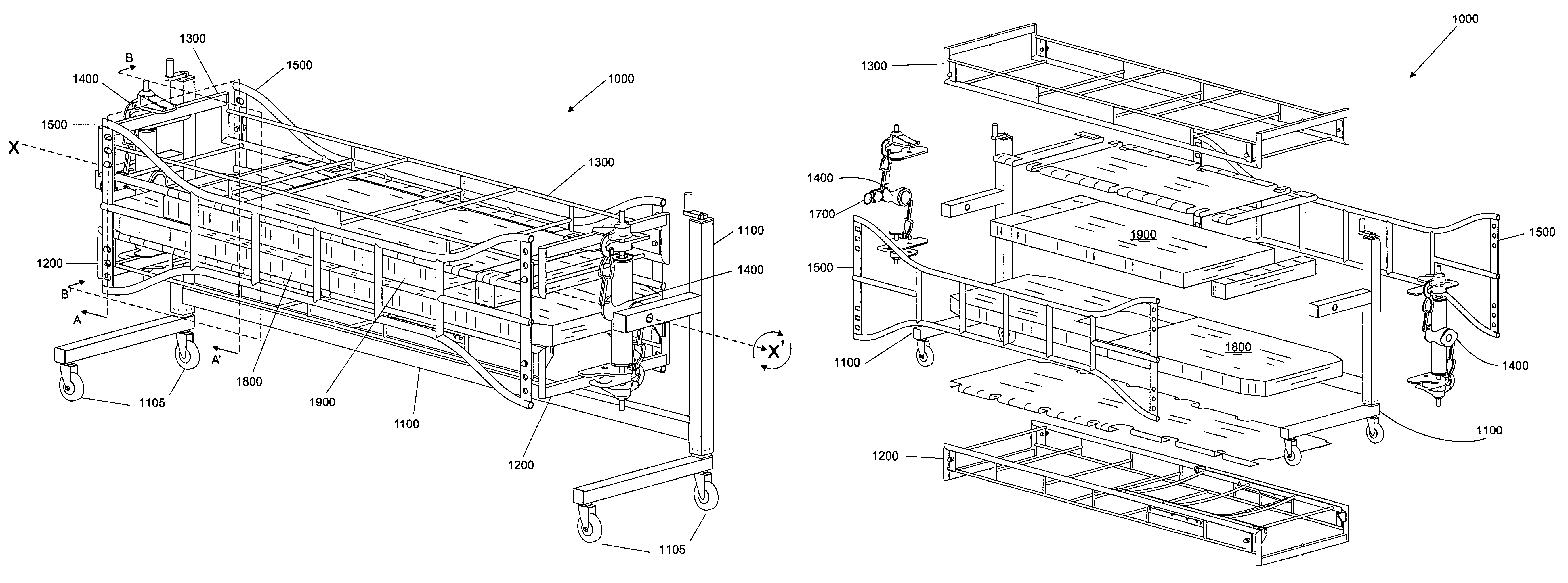
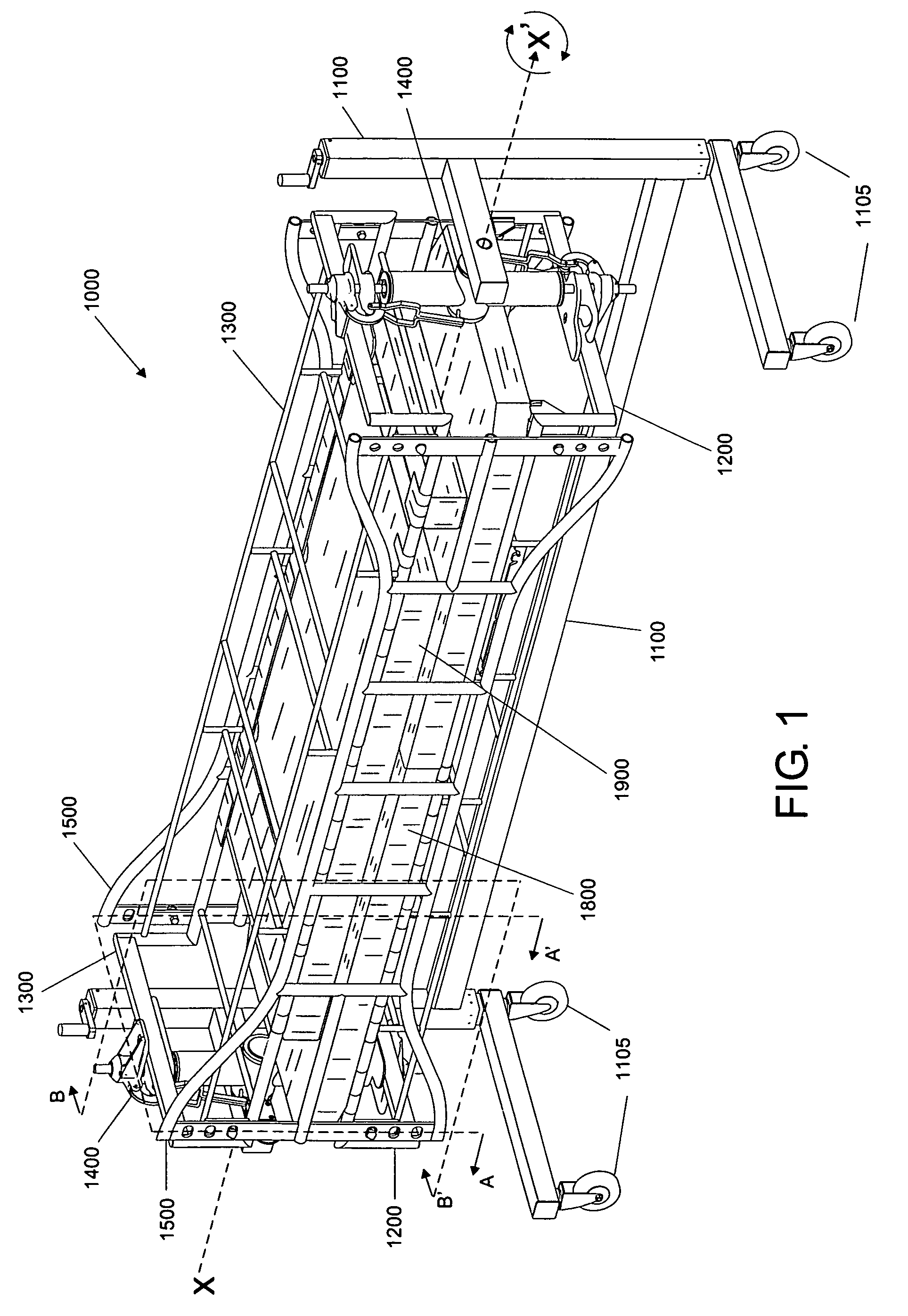
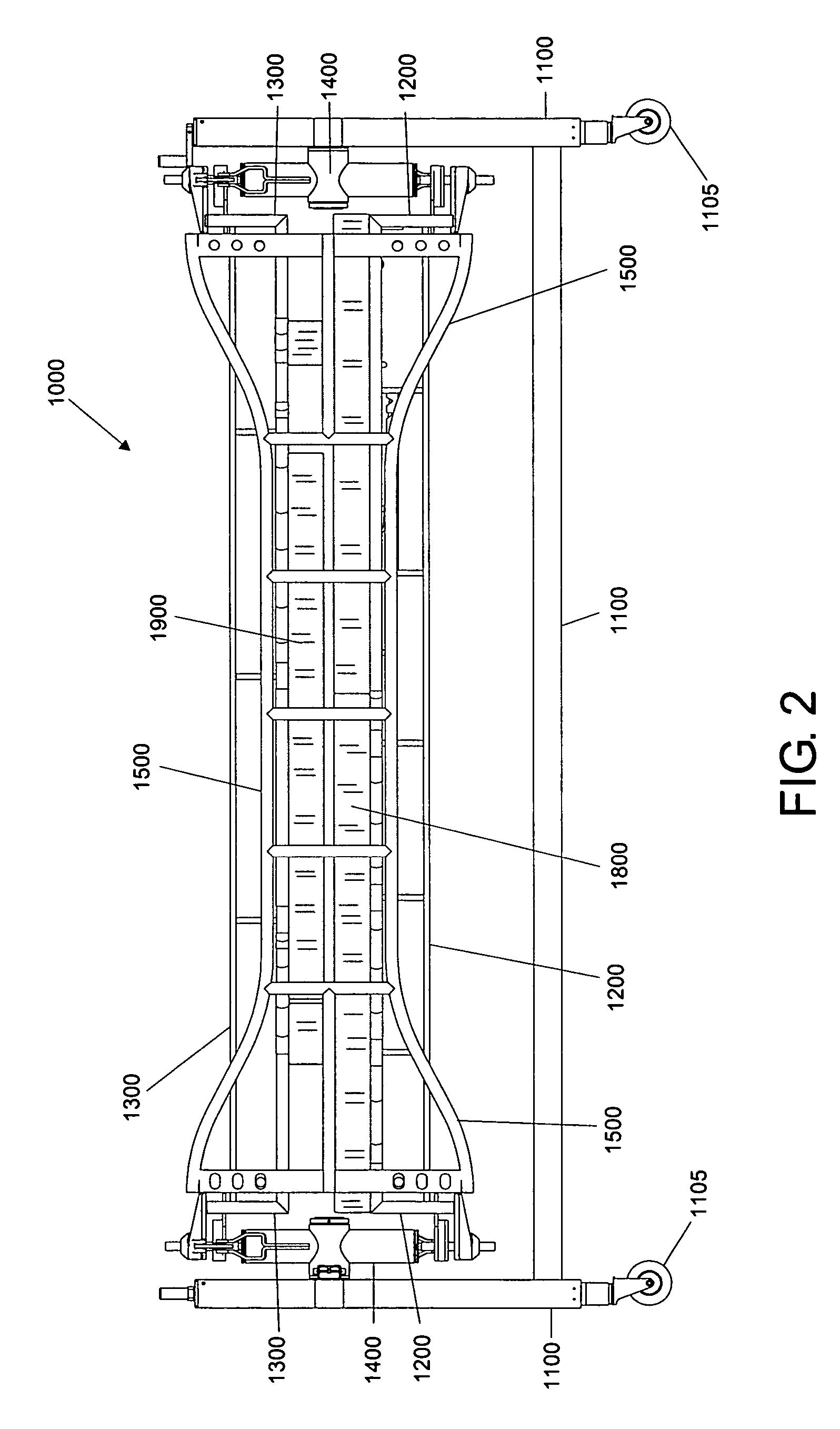
[0068]Referring to the appended drawings and more specifically to FIGS. 1-3, a rotating therapeutic bed 1000 is shown which is constructed according to a particularly specific embodiment of the present invention, which must be considered only as illustrative and non limitative in nature, such rotating therapeutic bed 1000 comprising in general and in combination: A structural base 1100 which includes turn wheels 1105 that are located on its lower part to allow relocating the bed from one place to another; a first removable stretcher 1200 having a first mattress 1800 to provide support for a patient (shown only in FIG. 11A of the appended drawings with referral number 2000) who is laying on his back; a second removable stretcher 1300 having a second mattress 1900 being located in an inverted fashion and over the first stretcher and patient, who is laying between the mattresses of both stretchers; the second stretcher 1300 providing support to the patient who is laying face down when ...


PUM


Abstract

It is depicted a rotating therapeutic bed which comprises: a structural base including in turn wheels located on its lower portion to allow moving the bed from one place to another; a first removable stretcher with a first mattress to support the patient laying on his back; a second removable stretcher with a second mattress being placed in a reversed fashion and over the first stretcher and the patient, who is supported between the mattresses of both stretchers; the second stretcher supporting the patient laying face down when stretchers are rotated by 180° on a rotation axis crossing along the patient; front and rear stretcher mounting and rotation members rotationally mounted on the structural base; the first and second stretchers being longitudinally mounted with a vertical spacing between them in such stretcher mounting and rotation means, which allow also their rotation; and side barriers coupled to the longitudinal sides of the first stretcher, as well as of the second stretcher, such barriers covering the vertical spacing between such stretchers where the patient is laying, preventing the patient's limbs from protruding from stretchers when they are rotated.

Description

FIELD OF THE INVENTION[0001]The present invention relates to the techniques used in designing and manufacturing devices and apparatuses for therapeutic and medical use employed for the treatment of people suffering from partial or temporary paralysis and, more particularly, it relates to a rotating therapeutic bed.BACKGROUND OF THE INVENTION[0002]In modern society, there is a series of accidents that takes place often. In developed societies, accidents related to car traffic are one of the main causes of death. Likewise, many people who make it to survive those traffic accidents partially or fully lose their body motility control due to the injuries resulting from the abovementioned traffic events.[0003]In addition to accidents, whether they are car traffic ones or not, there are other causes resulting in the loss of voluntarily moving some part of one's body. Such causes may be an illness or injury at any points along the motor nerve system between the brain and the muscle fibers, ...

Claims


Application Information

Patent Timeline
Patent Type & Authority Patents(United States)
IPC IPC(8): A61G7/008A61G1/06A61G7/00
CPCA61G1/0293A61G7/001A61G1/0237A61G1/0212A61G7/008
Inventor LOPEZ-SANSALVADOR, RODRIGO
Owner CIATEQ A C
Why Eureka
Try Eureka