Ureteral access sheath

Active Publication Date: 2010-02-02
CR BARD INC
View PDF20 Cites 36 Cited by
  • Summary
  • Abstract
  • Description
  • Claims
  • Application Information

AI Technical Summary

Benefits of technology

[0025]Stated generally, the present invention comprises a ureteral access sheath which addresses the described shortcomings of prior art ureteral access sheaths such as those described above. Like the prior art devices, the proposed ureteral access sheath comprises two separate components: a sheath and a dilator. However, the proposed sheath differs from known prior art devices in that it comprises multiple lumens—a main working channel and one or more secondary lumens. A secondary lumen integral with the ureteral access sheath can be used to irrigate the surgical field. Thus it is not necessary to rely

Problems solved by technology

However, the proposed sheath differs from known prior art devices in that it co

Method used


Image

  • Ureteral access sheath
  • Ureteral access sheath
  • Ureteral access sheath

Examples


Embodiment Construction

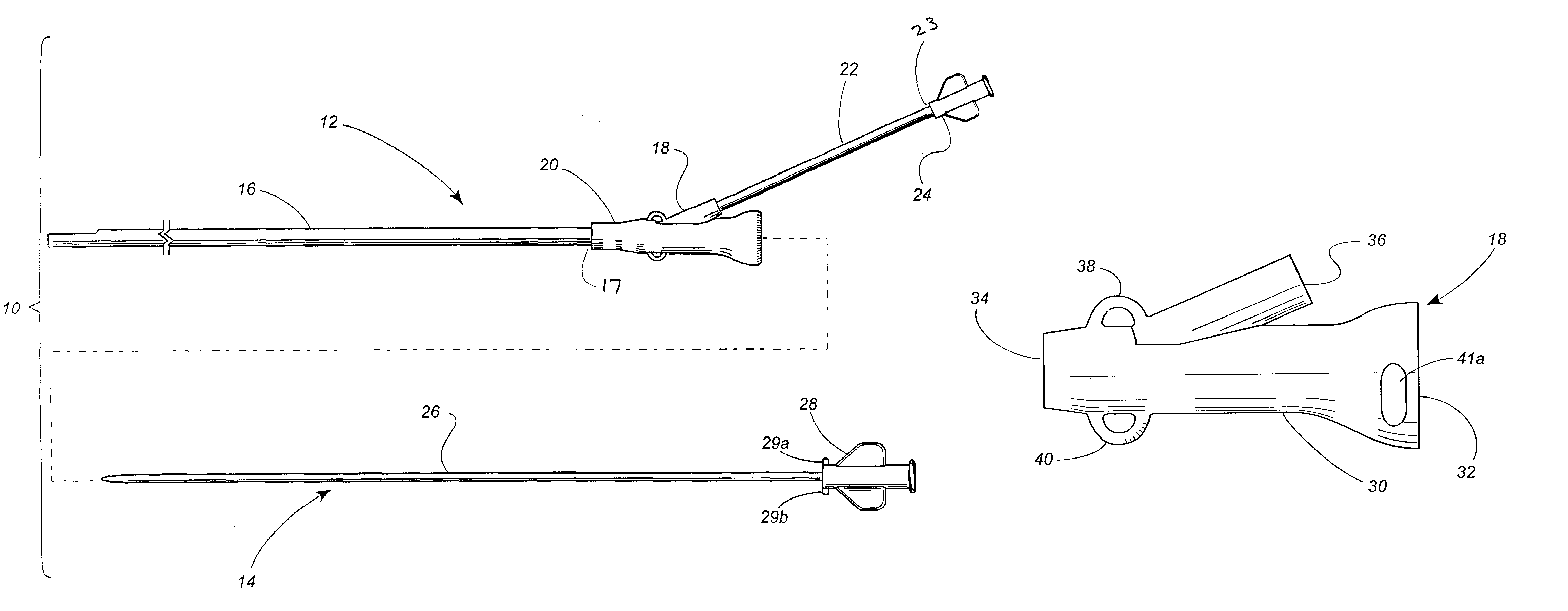
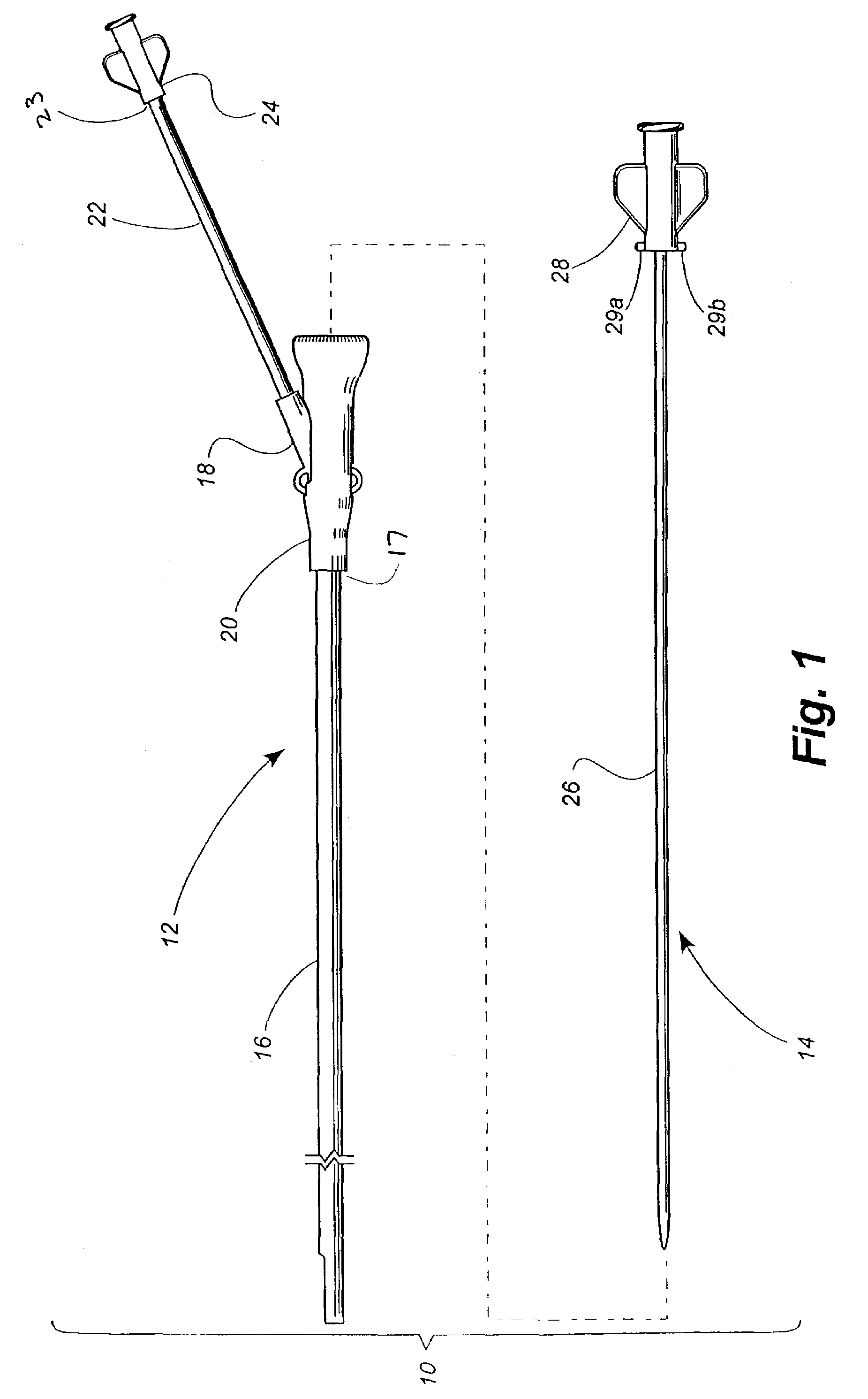
[0059]Referring now to the drawings, in which like numerals indicate like elements throughout the several views, FIG. 1 depicts a ureteral access sheath according to a disclosed embodiment of the present invention. The ureteral access sheath 10 comprises a sheath assembly 12 and a dilator assembly 14, which fits within the sheath assembly 12 when the ureteral access sheath 10 is being positioned within a patient.

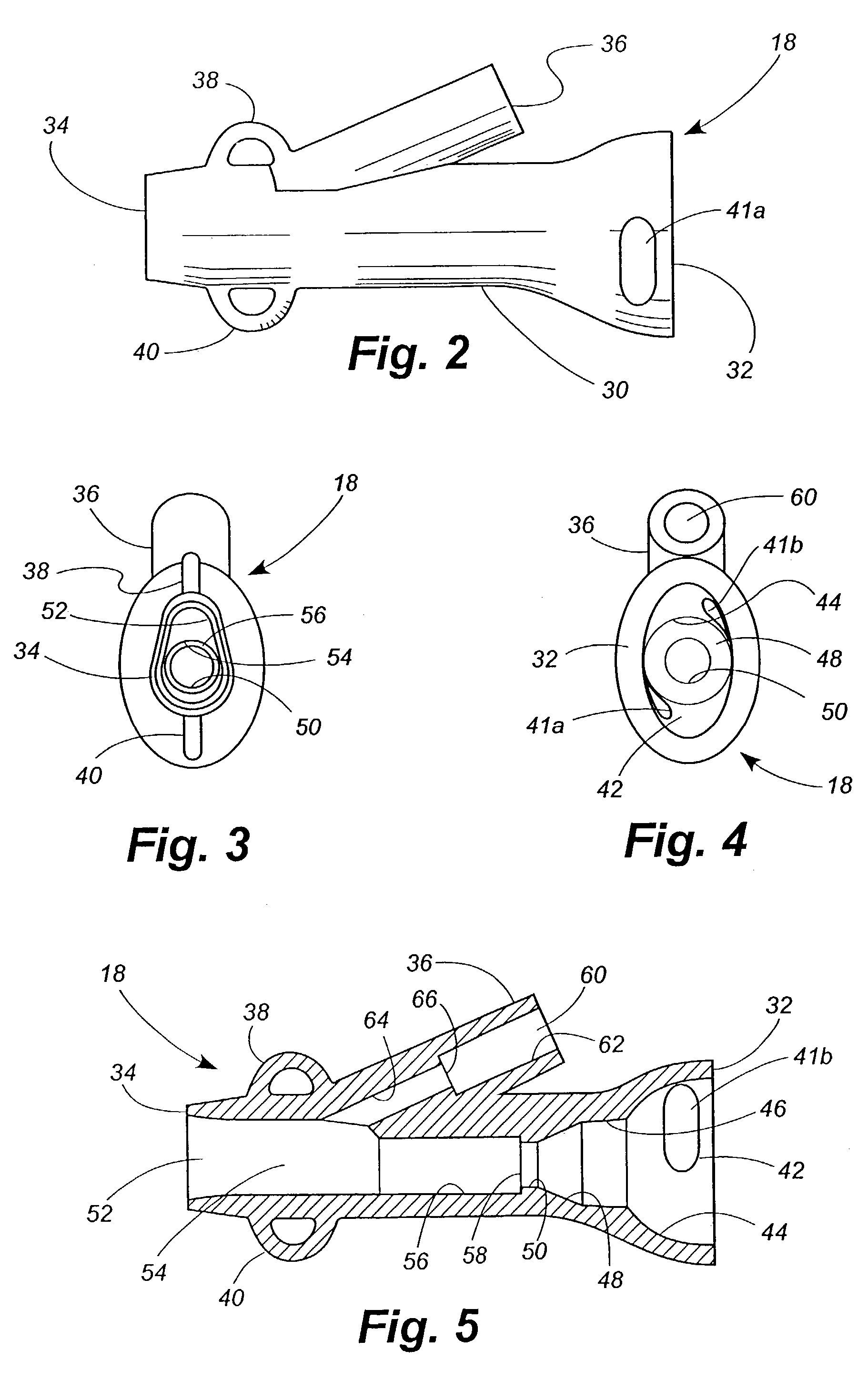
[0060]The sheath assembly 12 includes an elongated sheath tubing 16 having a distal end 17 and a proximal end coupled to a hub 18. The hub 18 is partially encased within an elastomeric cover 20. A leader tube 22 is also coupled to the hub 18. A female luer fitting 24 is mounted to the proximal end 23 of the leader tube 22.

[0061]The dilator assembly 14 comprises a dilator tubing 26 having a dilator luer 28 attached to the proximal end of the tubing. A pair of locking tabs 29a, b are formed or otherwise provided at a distal portion of the luer 28.

[0062]FIG. 1 is intended to pr...


PUM


Abstract

A ureteral access sheath comprises a sheath assembly having a main lumen and one or more secondary lumens. The sheath assembly can be configured with medical devices in both lumens, for example, a ureteroscope in the main working channel, and a guidewire, stone basket, grasper, laser fiber, or other surgical instrument in the secondary working channel. Or the sheath assembly can be configured with a medical device in one channel and the other lumen coupled to an irrigation means, such that irrigation of the surgical field can be efficiently accomplished even though the main working channel is substantially completely occupied by, e.g., a ureteroscope. Or the sheath assembly can be configured for irrigation through one lumen and aspiration through the other lumen, thereby creating a turbulent flow which washes the surgical field to facilitate removal of particles and debris.

Description

TECHNICAL FIELD[0001]The present invention relates generally to surgical devices and relates more specifically to a ureteral access sheath for creating an access channel from the external meatus to a location within the ureter of a patient.BACKGROUND OF THE INVENTION[0002]It is known to use a ureteral access sheath for creating an access channel from the external meatus to a location within the ureter of a patient to perform surgical procedures within the ureter and / or kidney. With an established channel to the ureter, a surgeon is able to insert and to withdraw a ureteroscope or other instrument more rapidly and with limited trauma to a patient's urinary system.[0003]A typical prior art ureteral access sheath includes two subassemblies: a dilator and a sheath. The dilator is placed within the sheath, and the dilator and sheath combination is advanced through the urethra, through the bladder, and to the ureter. The dilator is then withdrawn, leaving the sheath in place. A ureterosco...

Claims


Application Information

Patent Timeline
IPC IPC(8): A61M25/00A61B1/307
CPCA61B1/307A61M25/01A61M25/0032A61M25/0097A61M2025/0037A61M2025/0177A61M25/0662A61B1/32A61B17/0218A61B2017/0225A61M25/09A61M29/02
Inventor KNAPP, TRACEY E.
Owner CR BARD INC
Why Eureka
Try Eureka