Automated network to SAN topology linkage

a network topology and automatic technology, applied in the field of network communication, can solve the problems of manual processes that are prone to human error, and no practical technique for auto-discovery of linkage between san and network topologies, and achieve the effects of reducing the likelihood of human error causing inaccurate mapping, facilitating recalculation of accurate mappings, and facilitating localization and troubleshooting connectivity problems

Active Publication Date: 2010-02-02
CIENA
View PDF13 Cites 8 Cited by
  • Summary
  • Abstract
  • Description
  • Claims
  • Application Information

AI Technical Summary

Benefits of technology

[0008]One advantage of the invention is that the likelihood of human error causing inaccurate mapping is reduced. Another advantage is that updated mappings may be easily generated, thereby facilitating recalculation of accurate mappings which reflect changes in network topology. Another advantage is that these accurate mappings can be used to easily localize and troubleshoot connectivity problems in the SAN especially when it happens at the connection points between the SAN devices and the interconnecting network.

Problems solved by technology

However, there is no practical technique for auto-discovery of linkage between the SAN and network topologies.
The linkage can be manually calculated, but manual processes are prone to human error and require recalculations following topology changes in order to maintain accurate modeling.

Method used


Image

  • Automated network to SAN topology linkage
  • Automated network to SAN topology linkage
  • Automated network to SAN topology linkage

Examples


Embodiment Construction

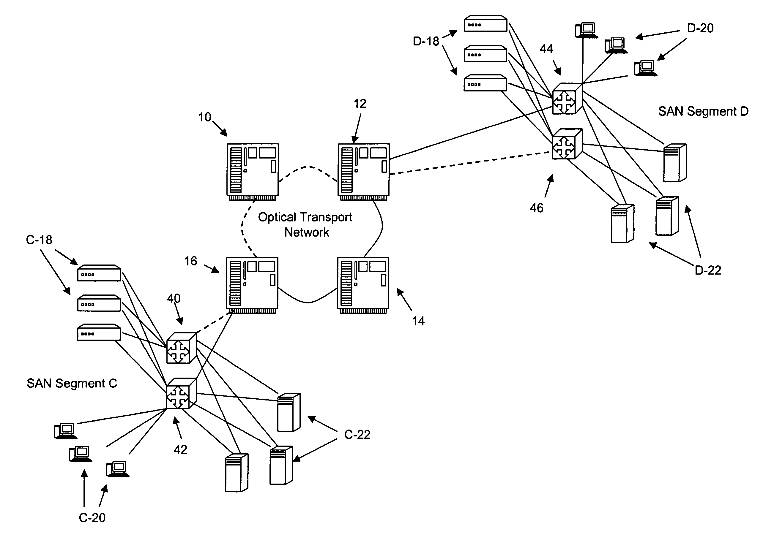
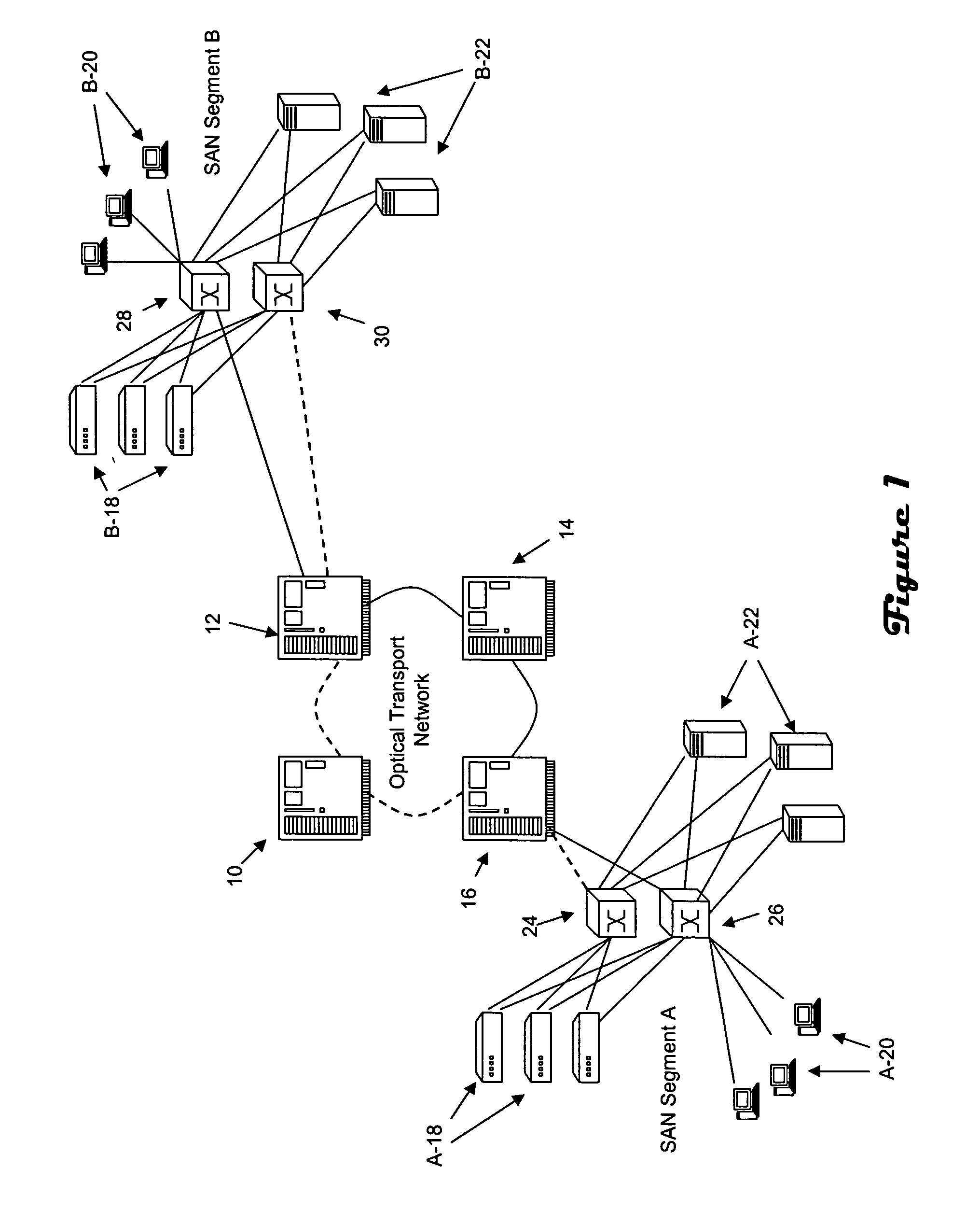
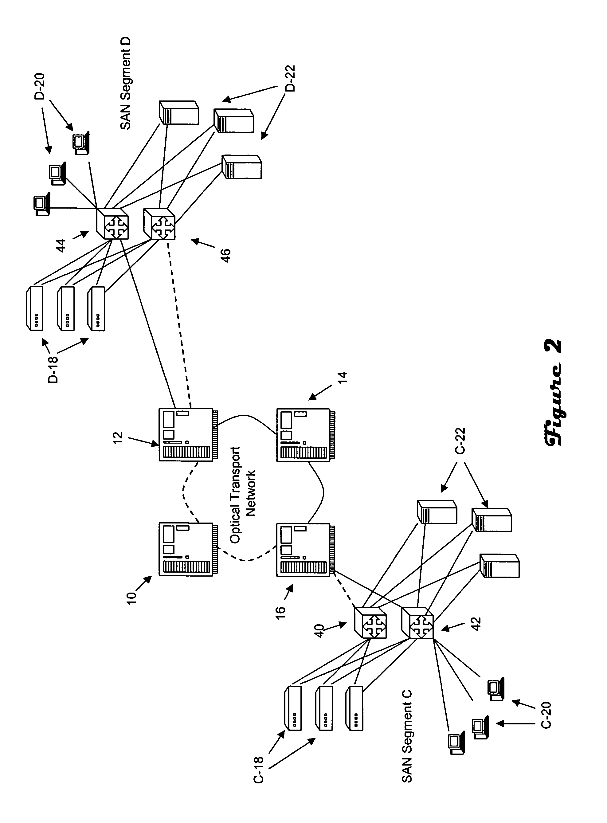
[0013]Referring to FIG. 1, segments A, B, of a SAN are interconnected via an optical transport network. The optical transport network includes optical switches 10, 12, 14, 16 which are connected in a SONET / SDH ring architecture. It should be recognized however that the optical switches could alternatively be connected in a mesh architecture. Each SAN segment includes servers 18, hosts 20 and storage arrays 22 that are interconnected via Fibre Channel switches 24, 26, 28, 30. The Fiber Channel switches provide connectivity between devices in the SAN segment, and also to the optical network. The Optical segments may employ the Generic Framing Procedure (“GFP”) protocol which includes an encapsulation method that allows Fibre Channel SAN traffic to be carried efficiently over SONET / SDH networks.

[0014]The optical transport network is transparent to the SAN devices. In particular, SAN devices have sufficient information to identify other devices in the SAN, including devices in other SAN...


PUM


Abstract

Collection of topology mapping linkage information between a Storage Area Network (“SAN”) and a transparent interconnecting transport network is at least partially automated. Physical topology information is gathered by detecting use of a physical path between a port of a first SAN device and a port of a second SAN device logically proximate to the transport network. This may be accomplished by discovering World Wide Names of end-points in a Fibre Channel SAN, and discovering Media Access Control addresses of end-points in an Ethernet SAN. The discovered physical topology information is then employed with known transport network logical topology information to determine which logical path or paths are associated with the physical path, i.e., to generate a mapping.

Description

CROSS-REFERENCE TO RELATED APPLICATIONS[0001]A claim of priority is made to U.S. Provisional Patent Application 60 / 542,116, entitled AUTOMATED NETWORK TO SAN TOPOLOGY LINKAGE TO GENERATE PHYSICAL AND LOGICAL END TO END TOPOLOGY MAPS, filed Feb. 5, 2004.FIELD OF THE INVENTION[0002]This invention is generally related to network communications, and more particularly to network-to-SAN topology mapping.BACKGROUND OF THE INVENTION[0003]Improvements in network communications have enabled introduction of networked services and products that perform functions previously implemented on a relatively local basis. For example, Storage Area Networks (“SANs”) provide a storage resource with similar performance to local storage such as Network Attached Storage (“NAS”). A SAN is a subnetwork of shared storage devices that may be employed relatively transparently by devices on a Local Area Network (“LAN”) or Wide Area Network (“WAN”). In particular, a SAN architecture allows storage resources such as...

Claims


Application Information

Patent Timeline
Patent Type & Authority Patents(United States)
IPC IPC(8): H04L12/28
CPCH04L41/12H04L49/357H04L49/65
Inventor MONGA, INDERMOHANSCHOFIELD, BRUCEMILLER, PIERRE
Owner CIENA
Why Eureka
Try Eureka