Imaging device for radiation treatment applications

a radiation treatment and imaging device technology, applied in the field of radiation medicine, can solve the problems of limited movement of rigid attachment of the arms that attach the x-ray source and the imager to the gantry, and limited ability to mov

Active Publication Date: 2010-02-02
VARIAN MEDICAL SYSTEMS
View PDF75 Cites 103 Cited by
  • Summary
  • Abstract
  • Description
  • Claims
  • Application Information

AI Technical Summary

Benefits of technology

[0006]A radiotherapy clinical treatment machine is described having a rotatable gantry and an imaging device with articulating robotic arms to provide variable positioning and clearance for radiation treatment applications. According to one aspect of the invention, a first and second robotic arms are pivotally attached to the rotatable gantry, allowing the robotic arms to maneuver independently from the rotatable gantry.

Problems solved by technology

With these gantry designs the movement of the x-ray source and the imager are limited to the movement of the gantry.
That is, the arms that attach the x-ray source and the imager to the gantry are rigidly attached (e.g., stationary) or have limited ability to move in relation to the gantry.
Furthermore, they have limited ability to be moved or stored “out of the way” to allow a technician unrestricted access to the patient, especially if the patient is being treated inside the bearing housing the x-ray source and imager.
In addition, the inflexible manner in which the x-ray source and imager are attached to the gantry limits the movement of these treatment components independent from the movement of the gantry.
For example, when the gantry is rotated to a specific position both components move with it, and the limited positions in which these components can be placed puts constraints on system movement and patient accessibility.
Therefore, these designs limit the versatility of positioning an imaging beam and possibly even a treatment beam.
Another major disadvantage of such a system is the unintended consequence of mechanical flexure of the device.
That is, the sagging weight of the x-ray source and / or imager may cause a misalignment of the imaging beam relative to the treatment beam.
Such misalignment may result in unintended error in placing the target volume within the treatment beam thereby causing unintentional damage to healthy tissue and / or an inadequate dose delivered to the target volume during treatment.
Conventional radiotherapy devices do not have the capability to identify mechanical flexure in real-time and make corrections before administrating the treatment beam.

Method used


Image

  • Imaging device for radiation treatment applications
  • Imaging device for radiation treatment applications
  • Imaging device for radiation treatment applications

Examples


Embodiment Construction

[0013]In the following description, numerous specific details are set forth to provide a thorough understanding of the invention. However, it is understood that the invention may be practiced without these specific details. In other instances, well-known circuits, structures and techniques have not been shown in detail in order not to obscure the invention.

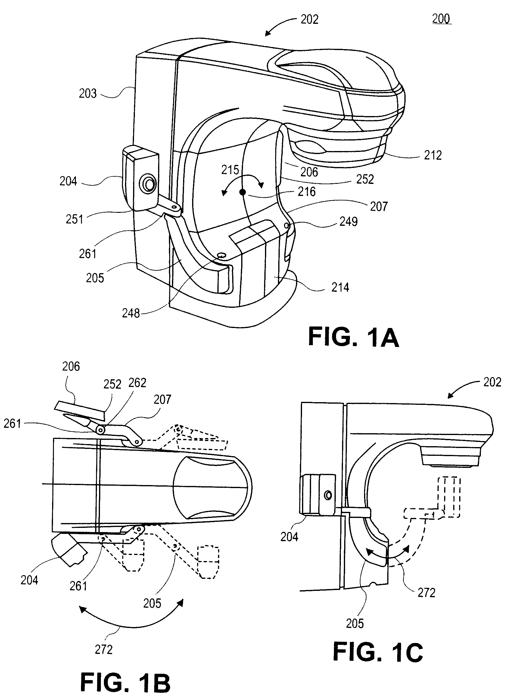
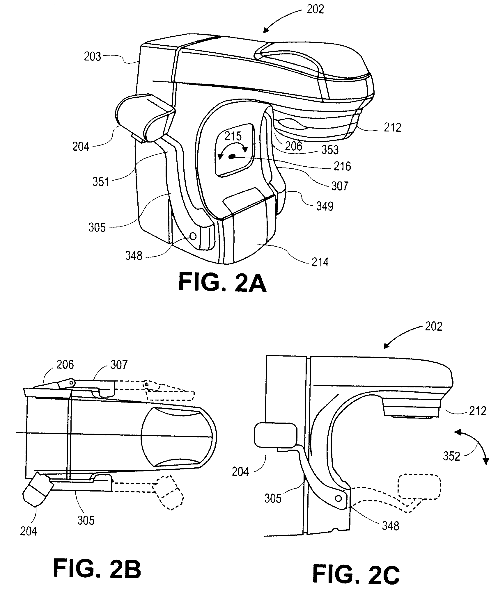
[0014]A radiotherapy clinical treatment machine is described having a rotatable gantry and imaging device with articulating robotic arms to provide variable positioning and clearance for radiation treatment applications. More specifically, a number of design configurations of the articulating robotic arms will be described that enable the positioning and re-positioning of a imaging source and a signal imager to provide versatility in placement and alignment to obtain imaging information useful in radiation treatment to a patient. Each device to be described has the ability to extend and retract the robotic arms to allow open acces...


PUM


Abstract

A radiotherapy clinical treatment machine is described having a rotatable gantry and an imaging device with articulating robotic arms to provide variable positioning and clearance for radiation treatment applications. According to one aspect of the invention, a first and a second robotic arms are pivotally coupled to the rotatable gantry, allowing the robotic arms to maneuver independently from the rotatable gantry.

Description

FIELD OF THE INVENTION[0001]The present invention pertains in general to radiation medicine. In particular, the invention involves imaging devices.BACKGROUND[0002]A technique to perform radiation therapy uses a radiotherapy device to target a radiation treatment beam onto a target volume (e.g., a tumor) of a patient. Such, radiation treatment beams emulate from a treatment radiation source, such as a megavoltage x-ray source. Here, the primary purpose of the x-ray source is to provide a sufficient dose of radiation to treat the target volume. Additionally such a radiotherapy device may include a separate imaging device used to image anatomy in the region of the target volume. This imaging device may use an imaging radiation source, such as a kilovoltage x-ray source. A radiation imager or detector is also used to capture the radiation after it passes through the patient. Information obtained from this imager can be used to adjust or verify correct positioning of patient anatomy and ...

Claims


Application Information

Patent Timeline
Patent Type & Authority Patents(United States)
IPC IPC(8): A61B5/05A61B6/00A61N5/10H05G1/02A61B6/02A61B6/08
CPCA61B6/4007A61B6/405A61B6/4233A61B6/4266A61B6/4458A61B6/482A61B6/587A61N5/1049A61B6/4452A61B6/4429A61B6/022A61B6/08A61N2005/1061
Inventor MANSFIELD, STANKOPELS, ROBERTGRAF, ULRICH MARTIN
Owner VARIAN MEDICAL SYSTEMS
Why Eureka
Try Eureka