

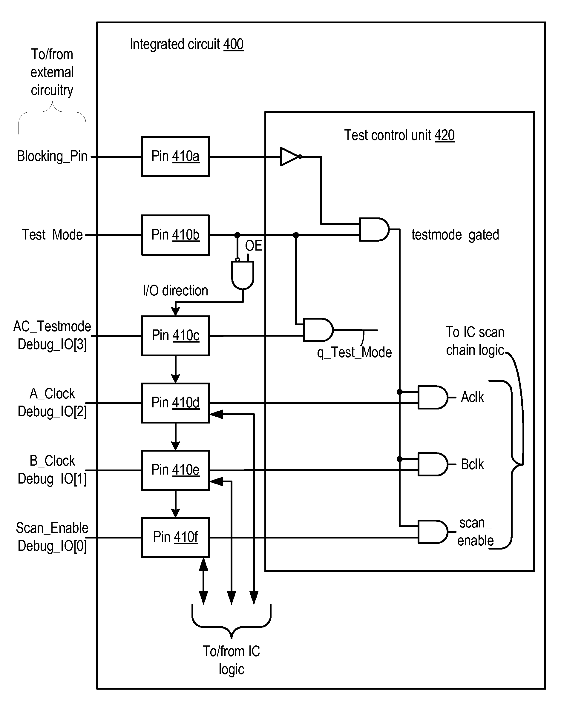
Integrated circuit with blocking pin to coordinate entry into test mode
a technology of integrated circuits and blocking pins, applied in error detection/correction, instruments, computing, etc., can solve the problems of increasing the possibility of error in implementation, affecting the functional verification of design, and affecting the practicality of complex designs including hundreds of millions of interconnected transistor devices
- Summary
- Abstract
- Description
- Claims
- Application Information
AI Technical Summary
Benefits of technology
Problems solved by technology
Method used
Image

Examples
Embodiment Construction
Introduction
[0019]As mentioned above, increasingly complex integrated circuit (IC) designs create challenges for implementing effective and reliable manufacturing test strategies. In the following discussion, one example of a complex integrated circuit implementing a multiple core, multithreaded processor is described in detail. Subsequently, particular techniques for implementing certain test features on such a complex circuit are discussed. It is noted, however, that the description of the multithreaded processor is merely exemplary, and that the test techniques described below may be implemented in any suitable type of IC, regardless of whether the circuit implements a general-purpose microprocessor, an embedded processor, custom functionality (e.g., an application-specific integrated circuit or ASIC), or any other functionality that may be realized by an IC.
Overview of Multithreaded Processor Architecture
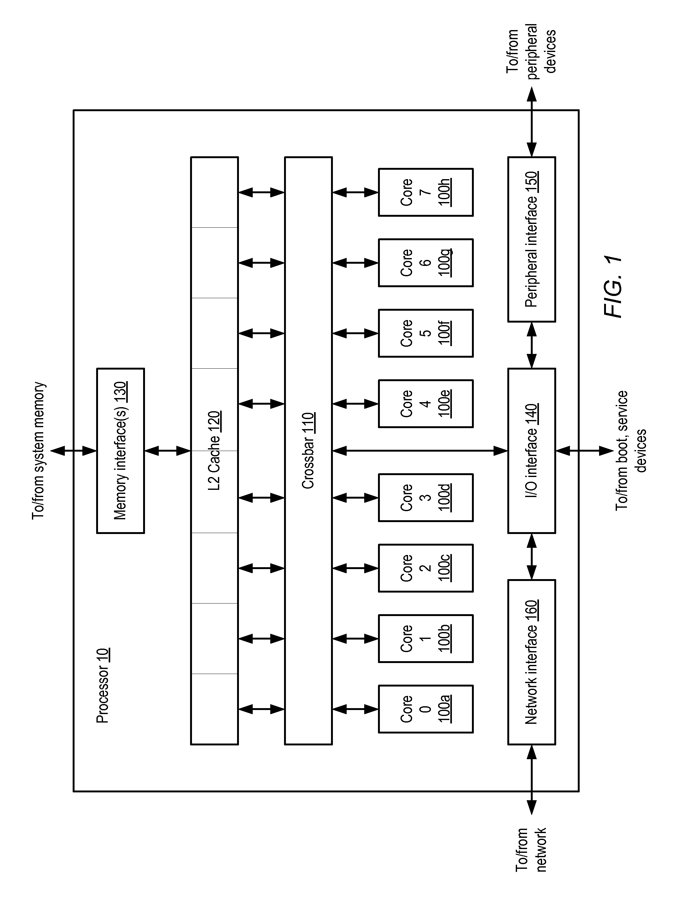
[0020]A block diagram illustrating one embodiment of a multithreaded proces...
PUM
 Abstract
Description
Claims
Application Information