Endoscope, in particular for tracheotomy

a technology of endoscope and trachea, which is applied in the field of endoscope, can solve the problems of inability to make a pinpoint precision incision into the trachea for the subsequently inserted tracheotomy cannula, and the light radiation angle is not uniform,

Inactive Publication Date: 2010-02-09
KARL STORZ GMBH & CO KG
View PDF20 Cites 33 Cited by
  • Summary
  • Abstract
  • Description
  • Claims
  • Application Information

AI Technical Summary

Benefits of technology

[0008]The angled arrangement, according to the invention, of the light-emitting distal end of the light guide relative to the longitudinal axis of the shaft means that the light is also radiated at an angle in the range of about 70° to about 110° relative to the longitudinal direction of the shaft, so that, even without the shaft of the endoscope being positioned obliquely, it is possible to produce, on the tracheal wall and on the skin of the throat area, a smaller light spot than is obtained merely with an obliquely configured window at the distal end of the light guide. Thus, the endoscope shaft can be introduced advantageously in the longitudinal direction of the trachea and does not have to be angled relative to the trachea. In this way, the advantage of pinpoint precision of the incision into the trachea at the desired site is achieved.
[0025]In conjunction with the angled positioning of the light-emitting distal end of the light guide, this measure has the advantage that the light guide is always connected to the shaft in the correct position of rotation in relation to the opening of the shaft, such that the light-emitting distal end of the light guide faces toward the opening.

Problems solved by technology

A difficulty that arises in an operation of this kind lies in determining the exact position of the incision for the subsequent tracheotomy cannula.
This results in an obtuse angle of radiation of the light relative to the longitudinal axis of the light guide.
To ensure a perpendicular incidence of the beam of light on the tracheal wall, the known endoscope has to be held obliquely relative to the longitudinal axis of the trachea, but the confined spaces in the region of the larynx and mouth through which the endoscope is introduced means this is not possible.
If the light spot visible from outside is smudged, however, the incision into the trachea for the subsequently inserted tracheotomy cannula cannot be made with pinpoint precision.
If this incision is not formed with pinpoint precision, the result of the tracheotomy may be compromised.

Method used


Image

  • Endoscope, in particular for tracheotomy
  • Endoscope, in particular for tracheotomy
  • Endoscope, in particular for tracheotomy

Examples


Embodiment Construction

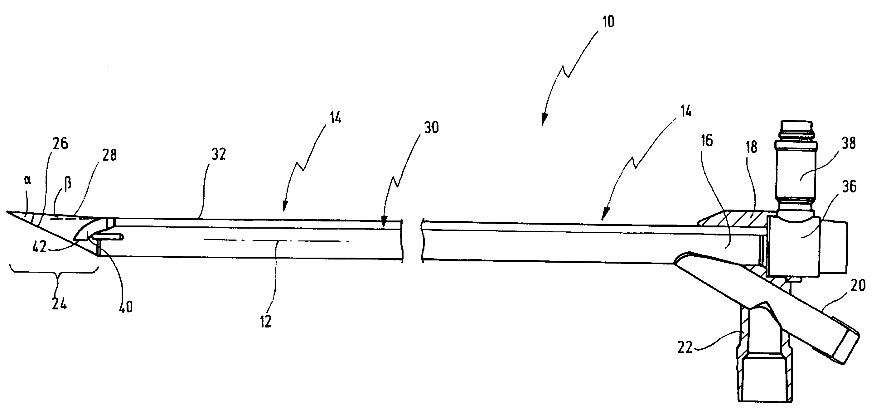
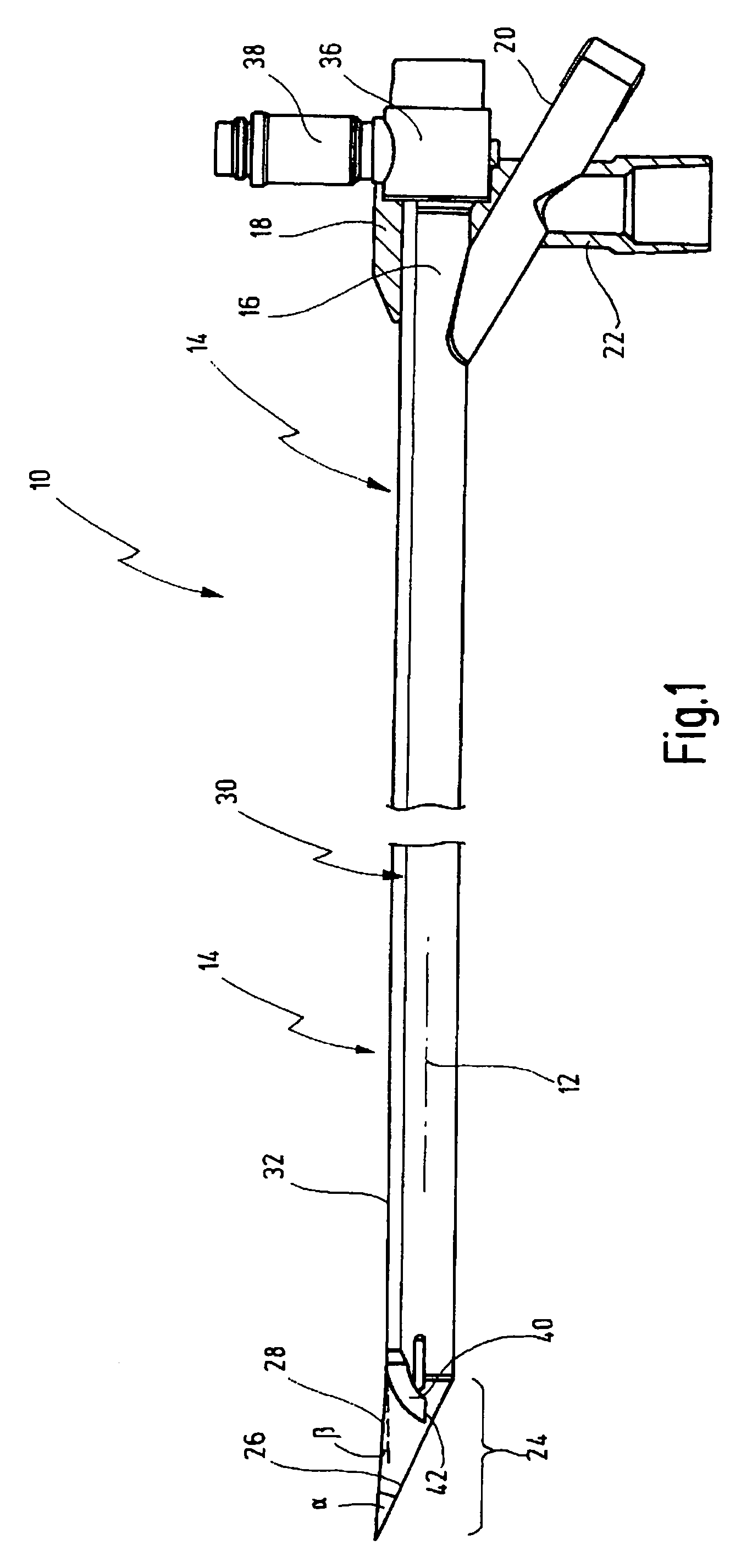
[0034]In FIGS. 1 and 4, an endoscope for tracheotomy is provided with the general reference number 10. It will be appreciated that the endoscope 10 can also be used in other medical disciplines.

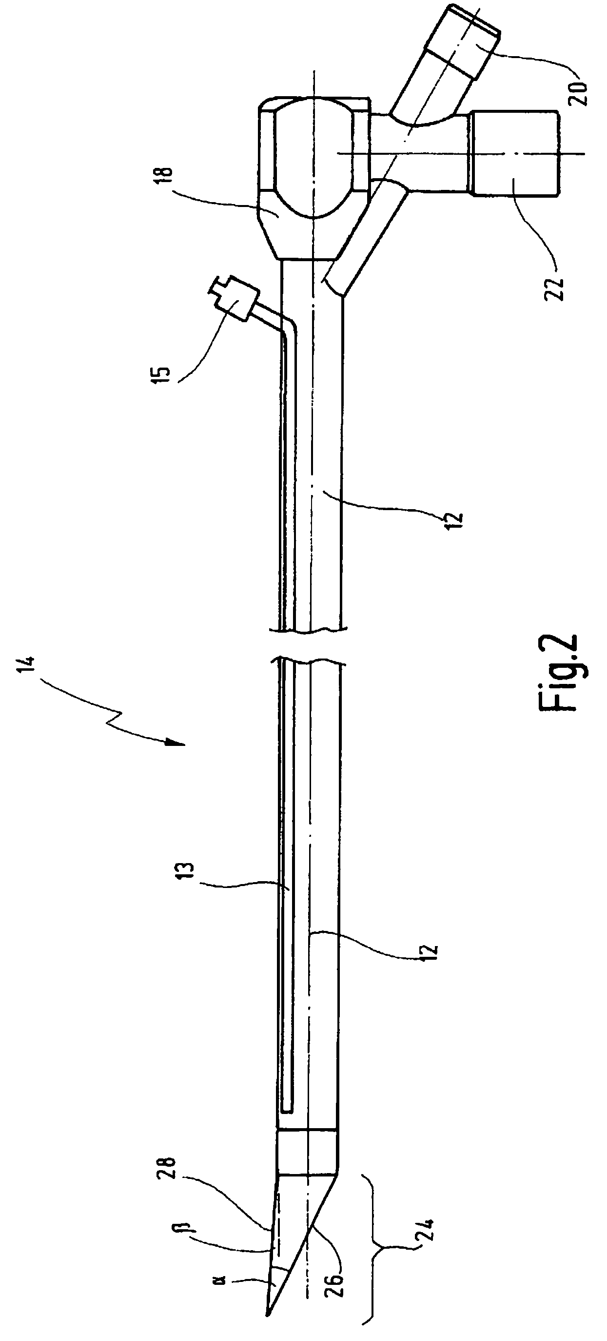
[0035]Components of the endoscope 10 are shown separately in FIGS. 2 and 3.

[0036]The endoscope 10 comprises a shaft 14 which has a longitudinal axis 12 and which, because of its length, is shown interrupted in the figures. The shaft 14 is in particular rigid. The longitudinal axis 12 is to be understood as the direction of longitudinal exension of the shaft 14.

[0037]At a proximal end 16, the shaft 14 has a coupling part 18 which will be described later and which is used to secure a light guide of the endoscope 10; a connector tube 20 which extends obliquely and is used for the insertion of auxiliary instruments, wires and the like; and a connector tube 22 which can be used, for example, for attachment of a ventilation line in the event of the endoscope 10 being used in a tracheotomy. FIG. 2, ...


PUM


Abstract

An endoscope, comprising an elongated tubular shaft for introducing into a body of a patient, the shaft having a longitudinal axis and a distal end, and further having an opening the distal end. A light guide is arranged along the shaft and has a light-emitting distal end, the light-emitting distal end being arranged in the area of the opening of the shaft in order to radiate light from the opening.

Description

BACKGROUND OF THE INVENTION[0001]The invention relates to an endoscope.[0002]Without limiting its general application, the endoscope according to the invention is particularly suitable for tracheotomy. An endoscope used for this purpose is also referred to as a tracheoscope or bronchoscope.[0003]In a tracheotomy procedure, when a patient whose normal breathing through the nose and mouth is impaired or no longer possible, an artificial route of respiration is established through the throat below the larynx. To do this, a trocar is used to create, from the outside, an incision through the throat and into the trachea, into which a tracheotomy cannula is later inserted through which the patient then breathes or can be ventilated.[0004]A difficulty that arises in an operation of this kind lies in determining the exact position of the incision for the subsequent tracheotomy cannula. For this purpose, as has been described in document DE 695 27 958 T2; an endoscope is introduced through th...

Claims


Application Information

Patent Timeline
Patent Type & Authority Patents(United States)
IPC IPC(8): A61B1/07A61B1/06
CPCA61B1/07A61B1/267A61M16/0472A61B1/0623A61B17/3415A61B90/361
Inventor KLEMM, ECKART
Owner KARL STORZ GMBH & CO KG
Why Eureka
Try Eureka