
Apparatus for adjusting static attitude of thin film magnetic head

a technology of static attitude and thin film magnetic head, which is applied in the direction of final product manufacturing, recording signal processing, instruments, etc., can solve the problems of flexure prone to be sprung back by its restoring force, dislocation from a desired static attitude, and discarding the assembled magnetic head uni

Inactive Publication Date: 2010-02-16
TDK CORPARATION
View PDF12 Cites 5 Cited by
  • Summary
  • Abstract
  • Description
  • Claims
  • Application Information

AI Technical Summary

Benefits of technology

[0012]It is an object of the present invention to provide an improved method and apparatus for adjusting static attitude of a magnetic head, wherein operation of obtaining a significant change in static attitude from bending a flexure at a small angle can be executed automatically.
[0018]When a flexure is bent for static attitude adjustment, a stress corresponding to the bending is generated in the flexure. According to the present invention, a laser beam is irradiated to a bent area of the flexure. In the laser-irradiated bent area, consequently, the stress can be relieved by heat due to the irradiation of the laser beam. As a result, the restoring effect of the flexure decreases in the laser-irradiated area, keeping the flexure bent at an angle close to the initial bending angle. This means that the flexure can be kept at a desired bending angle even if the initial bending angle is small. Therefore, a significant change in static attitude can be obtained from bending the flexure at a small angle.
[0027]It is apparent that this static attitude adjusting apparatus, which provides a static attitude adjusting system mainly of a CPU, enables automatic adjustment of the static attitude of the thin film magnetic head with a high degree of repeatability.
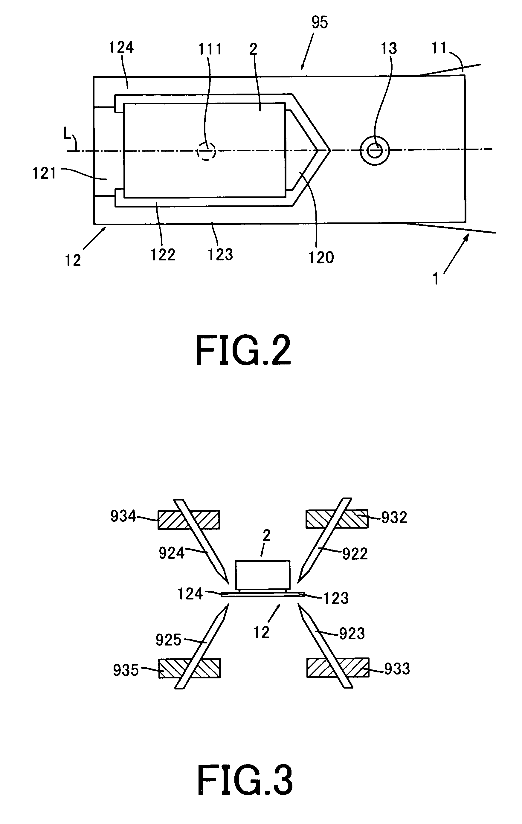
[0029]Preferably, the adjustment pins are disposed at a given angle with respect to the surfaces of the flexure. With this configuration, mutual interference, e.g., contact or overlap of the adjustment pins, can be avoided even if the thin film magnetic head and the flexure are miniaturized.
[0031]As has been described hereinabove, the present invention provides a method and apparatus for adjusting static attitude of a magnetic head, wherein operation of obtaining a significant change in static attitude from bending a flexure at a small angle can be executed automatically.

Problems solved by technology

However, the magnetic head unit is generally configured to have the magnetic head bonded to one end of the head support (or suspension) through an adhesive, which may cause displacement from a desired static attitude.
Since the magnetic head unit is manufactured by mounting the magnetic head, which is an expensive component manufactured through elaborate processes, on the head support, which is also an expensive high-precision component, it is not permitted to discard the assembled magnetic head unit as a defective product merely on the grounds that the static attitude angle of the magnetic head does not fall within a given range.
After being bent by the mechanical pressure, however, the flexure tends to be sprung back by its restoring force.
When the flexure is bent largely, a gap may be created between the flexure and a projection (or dimple) through which a load is applied from the load beam to the flexure, resulting in the occurrence of so-called dimple floating.
The dimple floating inhibits the load beam from applying a load onto the flexure, thus deteriorating the floating characteristic of the magnetic head.

Method used


Image

  • Apparatus for adjusting static attitude of thin film magnetic head
  • Apparatus for adjusting static attitude of thin film magnetic head
  • Apparatus for adjusting static attitude of thin film magnetic head

Examples


Embodiment Construction

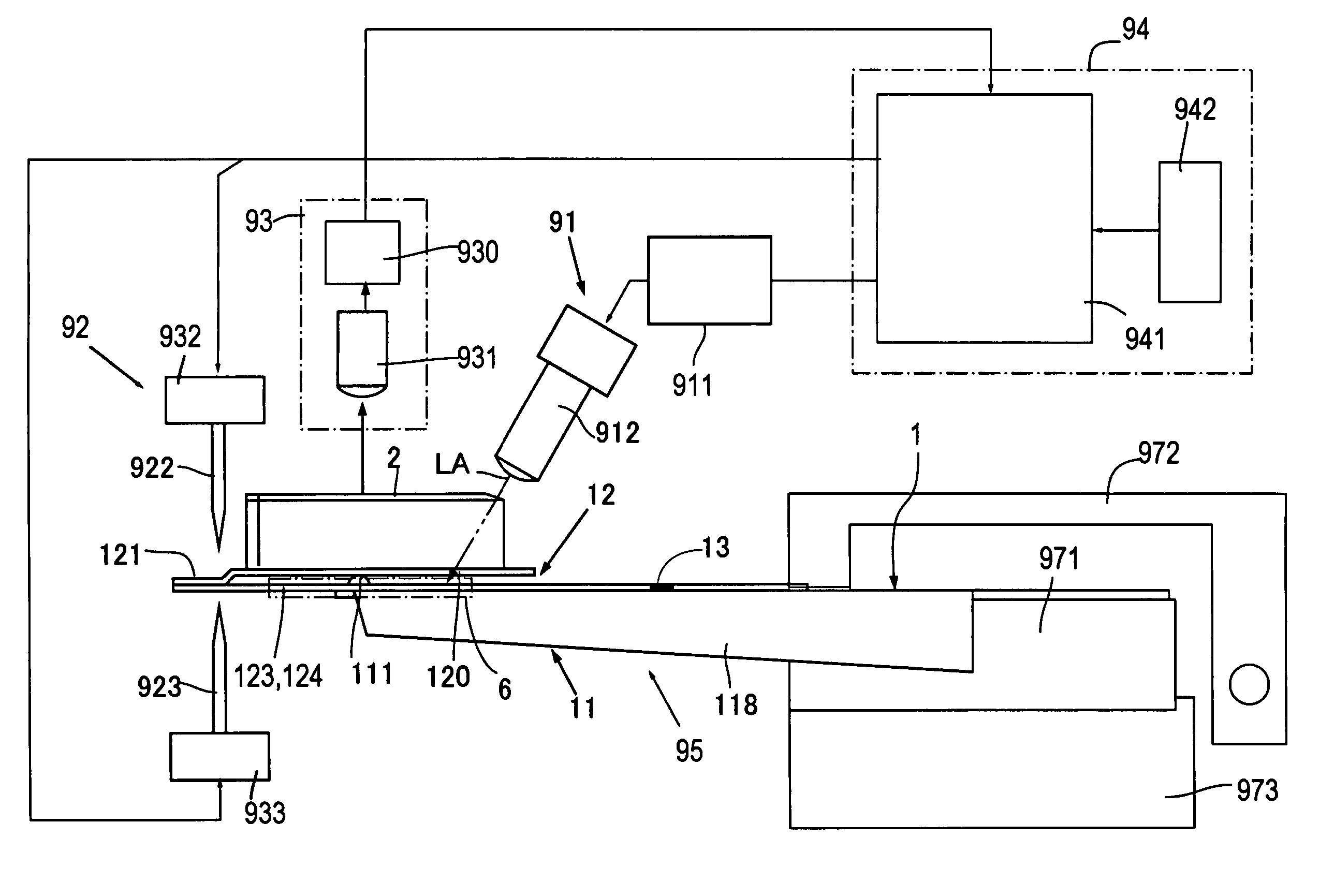
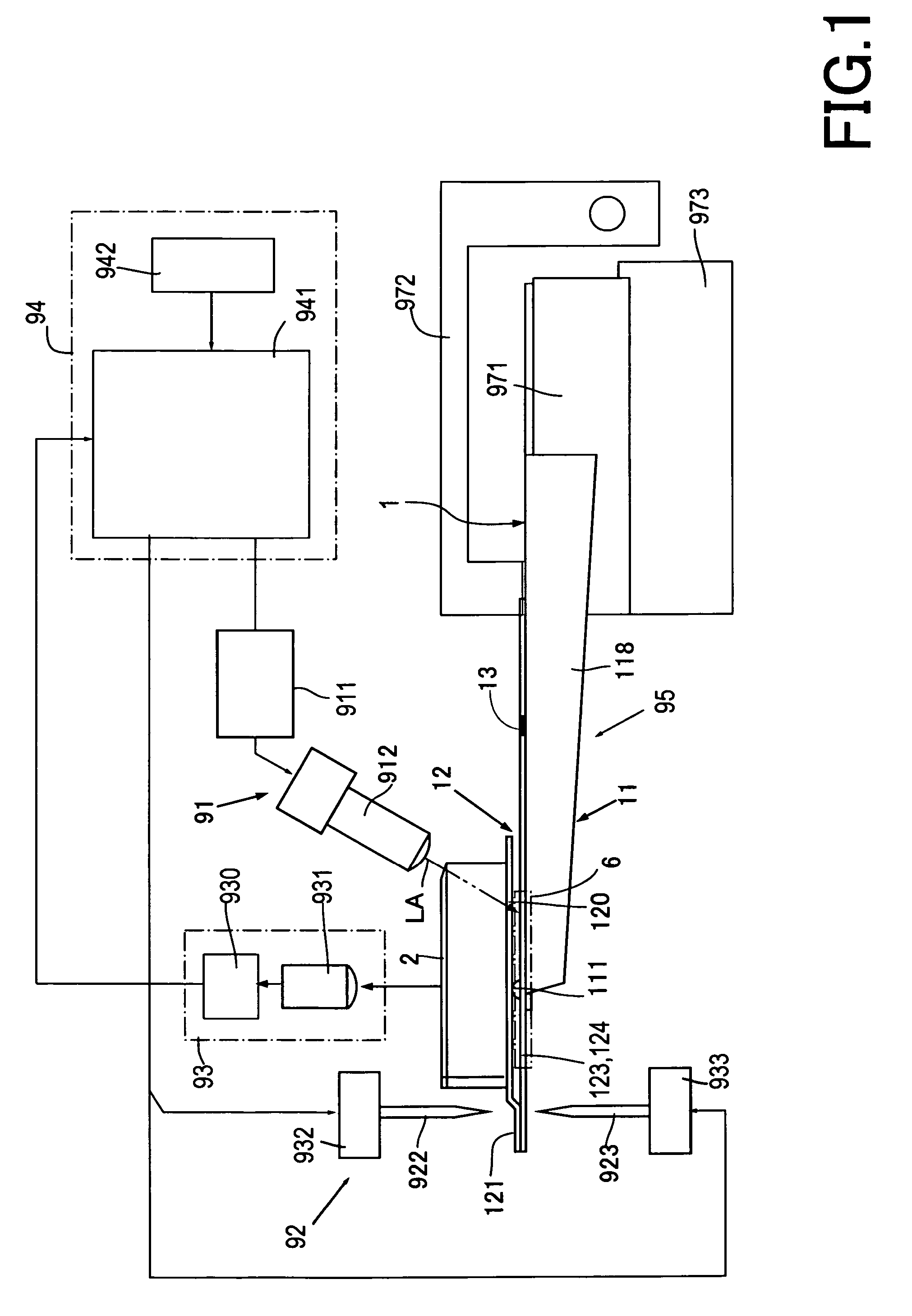
[0045]Referring to FIG. 1, a static attitude adjusting apparatus according to one embodiment of the present invention comprises a laser emitter unit 91, an adjusting unit 92, a measuring unit 93, and a computer system 94. The static attitude adjusting apparatus is configured to adjust the static attitude of a thin film magnetic head 2 of a magnetic head unit 95 shown in FIG. 2.

[0046]The magnetic head unit 95 comprises a head support (or head arm assembly) 1 and the magnetic head 2. The head support 1 comprises a load beam 11 and a flexure 12. The load beam 11 has a projection 111 located close to a free end thereof and on a longitudinal axis L thereof. At both lateral sides, the illustrated load beam 11 has two bent portions 118 to increase rigidity (see FIG. 1).

[0047]The flexure 12 is formed from a thin leaf spring and subjected to a pressing load from the projection 111 with one side of the flexure 12 attached to one side of the load beam 11 where the projection 111 is located. Th...


PUM

PropertyMeasurementUnit
surface temperatureaaaaaaaaaa
areaaaaaaaaaaa
static attitude angleaaaaaaaaaa

Abstract

Provided is an apparatus for adjusting static attitude of a thin film magnetic head attached to a flexure of a head arm assembly. The apparatus has an adjusting unit for bending the flexure, a laser emitter unit for irradiating a laser beam to a bent area of the flexure a measuring unit for measuring a static attitude angle of the thin film magnetic head, and a computer system including a CPU and a memory unit in which adjustment conditions corresponding to static attitude angles of the thin film magnetic head are previously ranked and memorized. The CPU is configured to retrieve from the memory unit a particular adjustment condition corresponding to a measured angle supplied from the measuring unit and supply the retrieved adjustment condition to the adjusting unit, enabling the adjusting unit to bend the flexure based on the retrieved adjustment condition supplied from the computer system.

Description

BACKGROUND OF THE INVENTION[0001]1. Field of the Invention[0002]The present invention relates to a method and apparatus for adjusting static attitude of a thin film magnetic head.[0003]2. Description of the Related Art[0004]It is an essential requirement of a floating-type magnetic head unit to hold at a higher accuracy the static attitude of a magnetic head supported with a head support for achieving high density recording and reproducing. The static attitude angles of the magnetic head unit include a pitch angle and a roll angle.[0005]However, the magnetic head unit is generally configured to have the magnetic head bonded to one end of the head support (or suspension) through an adhesive, which may cause displacement from a desired static attitude.[0006]Since the magnetic head unit is manufactured by mounting the magnetic head, which is an expensive component manufactured through elaborate processes, on the head support, which is also an expensive high-precision component, it is n...

Claims


Application Information

Patent Timeline
Patent Type & Authority Patents(United States)
IPC IPC(8): B23P19/00G11C5/12H01M10/14
CPCG11B5/4833G11B5/6005Y10T29/49036Y10T29/5313Y10T29/53165Y10T29/49032Y02P70/50
Inventor SHINDO, OSAMUMIZUNO, TORUTORII, TAKAO
Owner TDK CORPARATION
Learn More