
Vehicle dolly and method

Inactive Publication Date: 2010-02-16
SINK DWIGHT L
View PDF10 Cites 5 Cited by
  • Summary
  • Abstract
  • Description
  • Claims
  • Application Information

AI Technical Summary

Benefits of technology

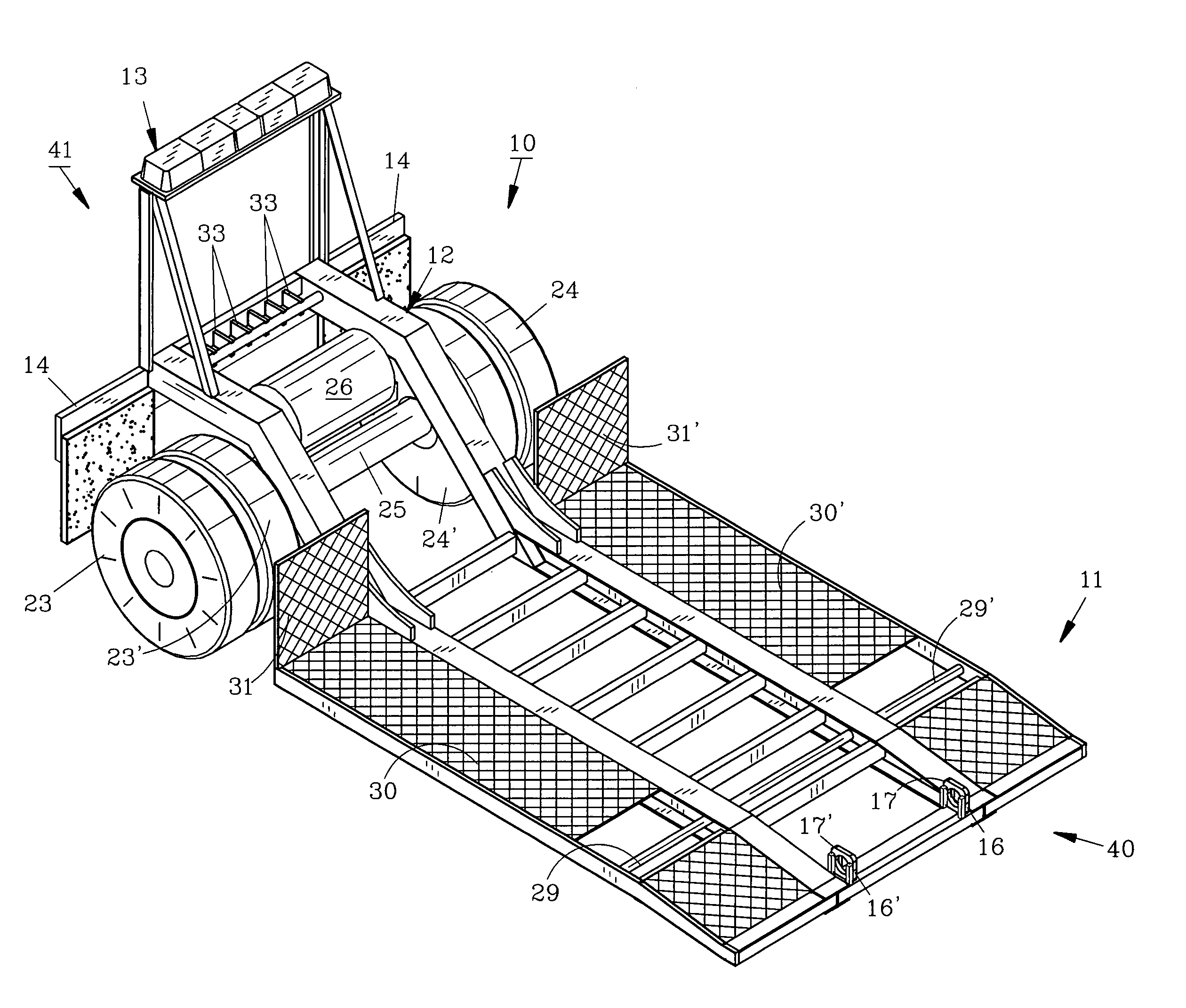
[0010]The aforesaid and other objectives are realized by providing a dolly formed from tubular steel by conventional welding techniques. At the proximal end of the dolly a ramp is provided for ease and convenience in loading tractors or other vehicles. Left and right rear wheel pairs are provided at the distal end of the dolly and mounted thereabove is an air tank for supplying emergency air to the wheel brakes in the event the pneumatic connections from the wrecker to the dolly are inadvertently ruptured. An array of lights is positioned on and elevated from the distal end of the dolly frame to warn following motorists during adverse weather or in poor light conditions. Planar beds are attached to the dolly frame on each side to support the rear tractor wheels. Between the ramp and beds on each side are tie-down bars for affixing chains or other tie-down components. Stops at the terminal end of each bed prevent excessive rearward movement of the tractor as it is positioned on the dolly. A pair of clamps at the proximal end of the dolly allow a secure connection between the dolly and the hydraulic arm of the wrecker when the unloaded dolly is towed. Electrical and pneumatic lines from the wrecker to the dolly are provided for the brake lights, warning lights and the brake system of the dolly as conventional.

Problems solved by technology

With modern tractors having wind-guards, the backwards towing is rarely implemented since the wind-guard causes a severe drag on the wrecker's momentum.
However, the tractor's owner and garage then require or request the wrecker driver to re-install the drive shaft upon arrival at the garage or other destination, a task most wrecker drivers are usually not qualified or capable of completing.
If the drive shaft is left removed the tractor owner is unhappy as he usually must hire a mechanic to properly reconnect the drive shaft at an additional expense.
However certain prior dollies do not have needed safety features for long distance towing.

Method used


Image

  • Vehicle dolly and method
  • Vehicle dolly and method
  • Vehicle dolly and method

Examples


Embodiment Construction

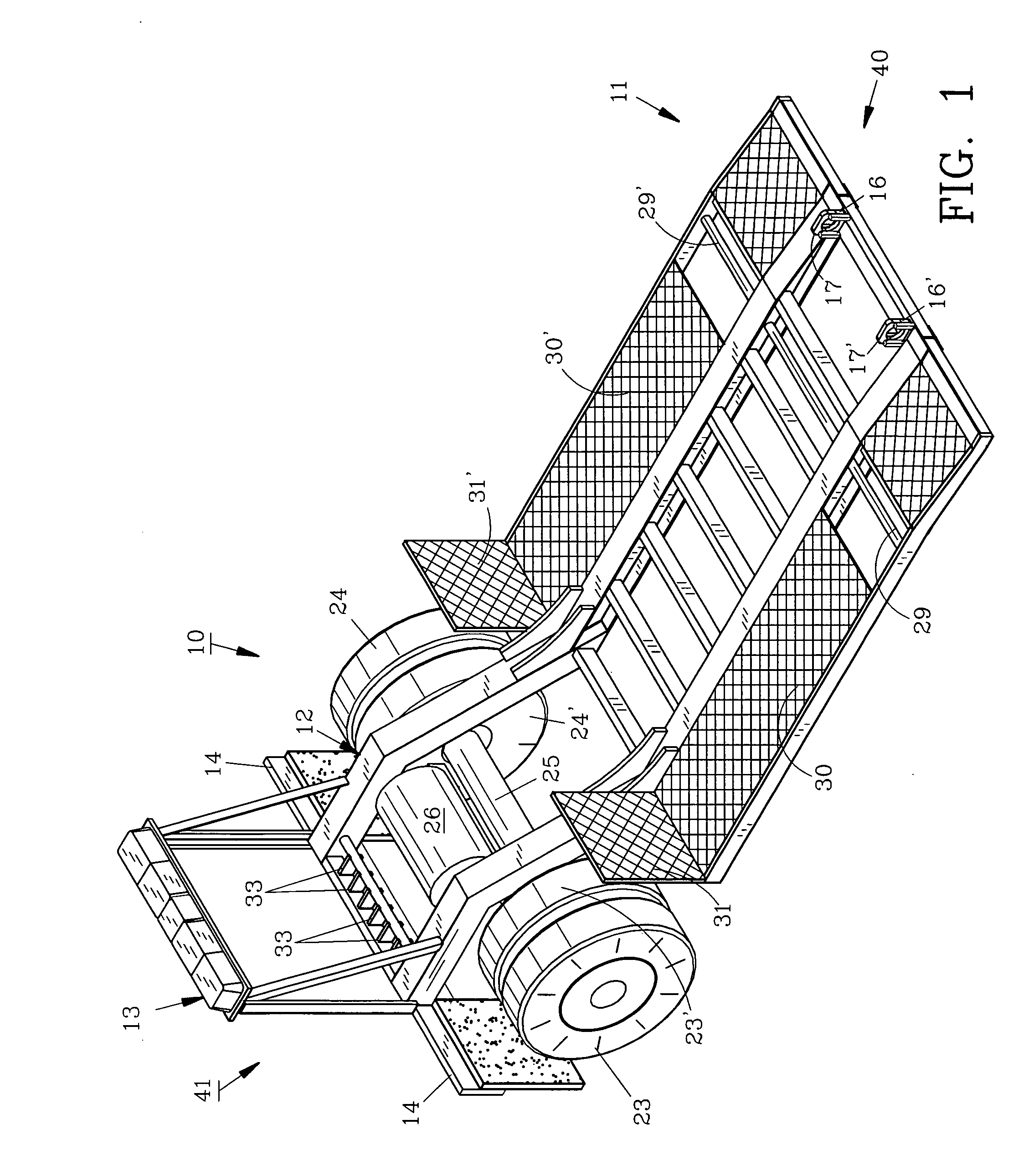
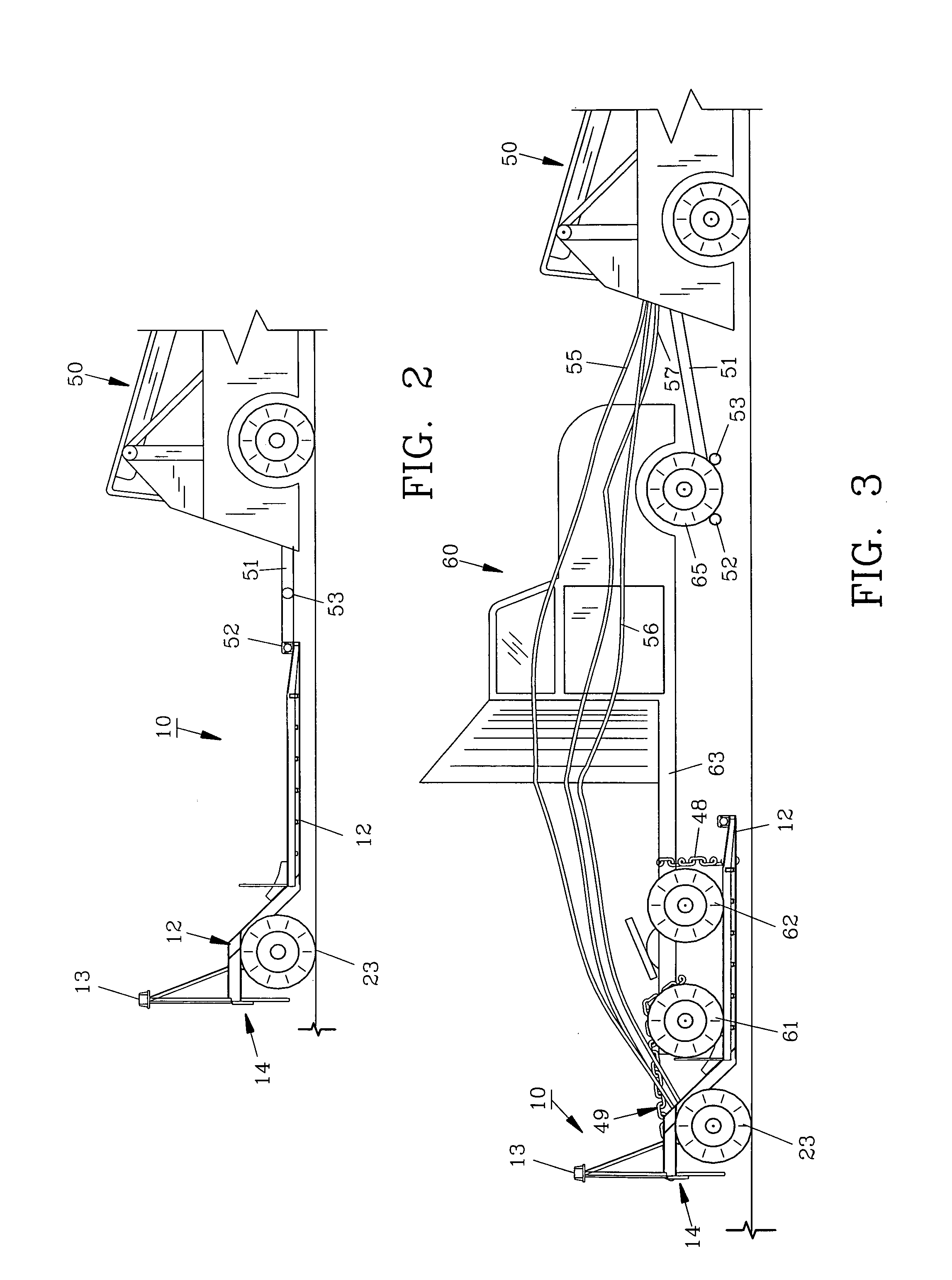
[0017]For a better understanding of the invention and its operation, turning now to the drawings, FIG. 1 shows a perspective view of preferred dolly 10 of the invention without a tractor or other vehicle thereon. Dolly 10 includes frame 12 formed from tubular steel or other suitable materials and extends from proximal end 40 to distal end 41. Frame 12 includes ramp 11 at proximal end 40 and warning array lights 13 and brake lights 14 at distal end 41, also shown in FIGS. 2 and 3. Warning array lights 13 are positioned in an elevated fashion above frame 12 to provide a warning to following motorists such as in adverse weather or poor lighting conditions. Frame 12 also provides U-shaped clamps 16, 16′ positioned at proximal end 40 attached as by welding or the like. As shown enlarged in FIGS. 4 and 5, clamps 16, 16′ include top 17, shown open in FIG. 4 and closed in FIG. 5, with base 19. Pin 18 passes through apertures in base 19 and top 17 for securing clamp 16 around wheel support 5...


PUM


Abstract

A dolly and method of use allow a disabled tractor to be efficiently and safely towed to a distant location. The dolly includes a ramp whereby the tractor can be easily rolled onto the dolly and secured thereto by tie-down chains. The method of use includes the steps of towing the dolly by wrecker to the disabled tractor, disengaging the dolly from the wrecker and connecting the wrecker to the tractor. The tractor is then urged by the wrecker up the ramp of the dolly where it is then secured. Electrical and pneumatic lines are connected from the wrecker to the dolly to operate brake lights, warning lights and the brake system of the dolly as conventional with trailers so the tractor can be safely towed to a distant location.

Description

FIELD OF THE INVENTION[0001]The invention herein pertains to a dolly for towing disabled vehicles and particularly pertains to towing trailer tractors using a dolly.DESCRIPTION OF THE PRIOR ART AND OBJECTIVES OF THE INVENTION[0002]Tractor-trailers transport most of the goods in the United States and in other countries. The trailer is usually attached to the tractor with a standard “fifth wheel” which provides ease and security in the connection. Tractors come in various sizes and types and most modern tractors employ a wind-guard to reduce air resistance for fuel economy as they travel. Wreckers and other towing vehicles are often employed to move disabled tractors from one location to a garage or repair yard distanced from the point of disablement. Tractors utilize a drive shaft for the rear wheels which must be removed before towing if the rear wheels remain on the ground. In the past, tractors were often towed in a “backward” posture as opposed to the wrecker whereby the rear whe...

Claims


Application Information

Patent Timeline
IPC IPC(8): B62D53/04
CPCB60P3/122
Inventor SINK, DWIGHT L.
Owner SINK DWIGHT L
Learn More