3D MEMS scanner for real-time cross-sectional endomicroscopy

A technology of micro-mirrors and scanning mirrors, which can be used in radiological diagnostic instruments, microscopes, and diagnostics using tomographic scanning, etc. It can solve the problems of 3D fast-axis scanning frequency limitation, high manufacturing complexity, and slow response time. , to achieve superior dynamic range, easy fiber optic connectivity, and increased imaging depth

Active Publication Date: 2018-11-09
RGT UNIV OF MICHIGAN
View PDF20 Cites 2 Cited by
  • Summary
  • Abstract
  • Description
  • Claims
  • Application Information

AI Technical Summary

Problems solved by technology

Although some designs can provide sufficient lateral in vivo scanning, but the design has limitations in the ability to scan with large out-of-plane displacements
Actuators based on shape memory alloys (nitinol) were used, for example, in the first generation of confocal endoscopes to provide large axial displacements (>250 µm), but these devices were slow and suffered from hysteresis phenomenon (hysteresis)
Other MEMS-based electrostatic scanners have been developed that have fast response times at low voltages, but sufficient Z-axis motion has not yet been achieved
Electrothermal devices can provide large axial displacements (>600 µm) at low voltages (~5 V), but the response time is in vivo too slow for imaging
Piezo scanners can achieve large DC displacements, but 3D fast-axis scanning frequency is limited and manufacturing complexity is high
Electromagnetic scanners have been developed with fast response times and good displacements, but the technology is difficult to scale down in size for most endoscopy applications

Method used


Image

  • 3D MEMS scanner for real-time cross-sectional endomicroscopy
  • 3D MEMS scanner for real-time cross-sectional endomicroscopy
  • 3D MEMS scanner for real-time cross-sectional endomicroscopy

Examples


Embodiment Construction

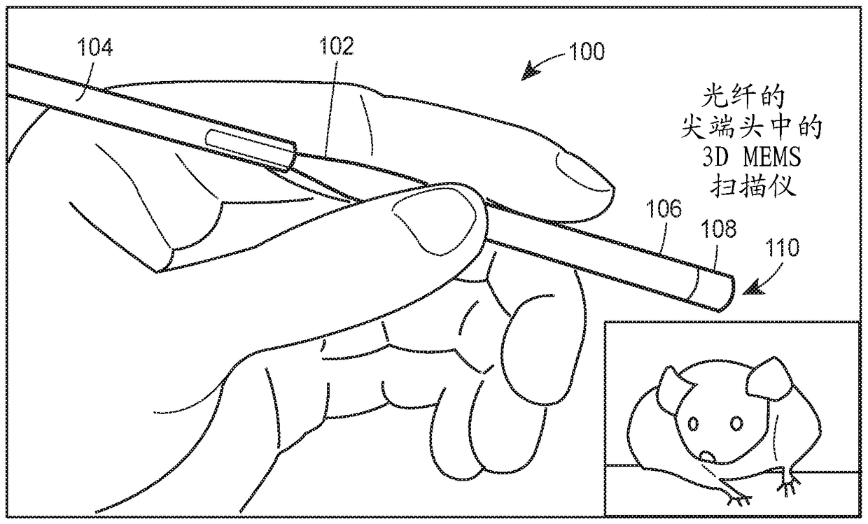
[0026] In general, in accordance with these various embodiments, techniques are provided for the design, fabrication, and implementation of a compact integrated monolithic three-dimensional (3D) MEMS scanner having dimensions that can be accommodated within an endoscopic device. In an example, a 3D MEMs scanner can be sized below about 10 x 10 mm 2 , less than about 5×5 mm 2 , below about 4×4 mm 2 and so on.

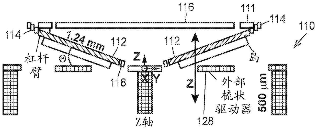
[0027]The 3D MEMS scanning techniques described herein are capable of producing both large angular deflections and out-of-plane displacements. For example, optical deflection angles greater than about ±10º, greater than about ±15º, greater than about ±25º, etc. are achievable in X-axis and Y-axis motion. The 3D MEMS scanner technology described herein can achieve such operating conditions by scanning along the z-axis at depths greater than about 200 μm, greater than about 300 μm, greater than about 400 μm, greater than about 500 μm, etc.

[0028] Scanning of full 3D ...


PUM


Abstract

An optical probe scanning assembly for use in an optical probe includes a mirror assembly that focuses an illumination beam path and a collection beam path at a region of interest within the sample. The illumination beam and the collection beam overlap to form a confocal beam region. The mirror assembly is movable in an x-axis direction and in a y-axis direction to scan the confocal beam region within the sample. The scanning assembly further includes a scanning suspension system including a gimbal assembly connected to the mirror assembly to allow the mirror assembly to rotate about one or more axes. The mirror is thereby adapted to scan along at least two different orthogonal planes, one of which extends vertically into the sample.

Description

[0001] Cross References to Related Applications [0002] This application claims the benefit of U.S. Provisional Application No. 62 / 264,645, filed December 8, 2015, entitled "3D MEMS Scanner for Real-Time Cross-Sectional Endomicroscopy," the entire contents of which are expressly incorporated herein by reference middle. [0003] Statement of Government Interest [0004] This invention was made with government support under CA142750 awarded by the National Institutes of Health. The government has certain rights in this invention. technical field [0005] The present disclosure relates generally to techniques for imaging tissue using optical instruments, and more particularly, to techniques for allowing real-time scanning using optical instruments. Background technique [0006] The brief description of the related art provided herein is for the purpose of generally presenting the context of the disclosure. The work of the presently named inventors, to the extent that they ...

Claims


Application Information

Patent Timeline
Patent Type & Authority Applications(China)
IPC IPC(8): G02B26/08A61B6/00G02B6/26
CPCA61B1/313A61B5/0068A61B5/0073A61B5/1459G02B21/0048G02B23/24G02B26/0841G02B26/103B81B3/0021G02B6/26
Inventor T.D.王H.李X.段Z.秋K.奥尔德姆
Owner RGT UNIV OF MICHIGAN
Why Eureka
Try Eureka