Optical coherence tomography system with reference arm capable of synchronously scanning three-view imaging

A technology of optical coherence tomography and synchronous scanning, applied in surgical navigation systems, using tomographic scanning for diagnosis, medical science, etc., can solve the problem that OCT imaging cannot cover blood vessels, achieve good adaptability, and improve the effect of imaging depth

Inactive Publication Date: 2017-12-19
江苏伊士嘉医疗科技有限公司
View PDF4 Cites 5 Cited by
  • Summary
  • Abstract
  • Description
  • Claims
  • Application Information

AI Technical Summary

Problems solved by technology

[0004] However, the blood in the blood vessel has strong scattering and absorption phenomena on the light signal

Method used


Image

  • Optical coherence tomography system with reference arm capable of synchronously scanning three-view imaging
  • Optical coherence tomography system with reference arm capable of synchronously scanning three-view imaging
  • Optical coherence tomography system with reference arm capable of synchronously scanning three-view imaging

Examples


Embodiment 1

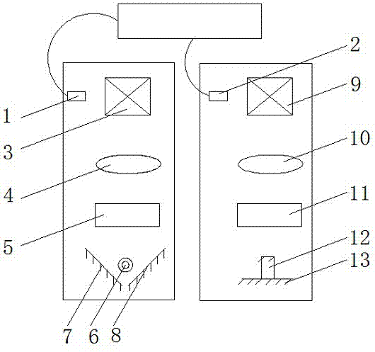
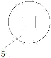
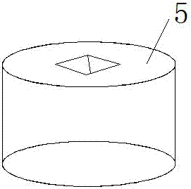
[0026] see figure 1 , figure 2 , image 3 and Figure 4 , an optical coherence tomography system with a reference arm synchronously scanning three-view imaging, including an OCT core component, a sample arm and a reference arm, the OCT core component is a spectral domain OCT core component; the sample end optical fiber of the OCT core component is connected to the The first fiber collimator 1 in the sample arm is connected, and the reference end fiber of the OCT core component is connected to the second fiber collimator 2 in the reference arm; the inside of the sample arm is sequentially provided with first The beam scanning galvanometer 3, the first focusing lens 4, the first focus shift waveplate 5 and the sample 6; and the first beam scanning galvanometer 3 and the first fiber collimator 1 are on the same horizontal line; the sample 6 Both sides are obliquely provided with a first sample arm plane mirror 7 and a second sample arm plane mirror 8; the inside of the refere...

Embodiment 2

[0029] see figure 1 , figure 2 , image 3 and Figure 5 An optical coherence tomography system for synchronously scanning three-view imaging with a reference arm, comprising an OCT core component, a sample arm and a reference arm, the OCT core component is a frequency-swept OCT core component; the sample end optical fiber of the OCT core component is connected to the sample The first fiber collimator 1 in the arm is connected, and the reference end optical fiber of the OCT core component is connected to the second fiber collimator 2 in the reference arm; the inside of the sample arm is sequentially provided with the first light beam from top to bottom The scanning galvanometer 3, the first focusing lens 4, the first focus shift wave plate 5 and the sample 6; and the first light beam scanning galvanometer 3 and the first optical fiber collimator 1 are on the same horizontal line; The first sample arm plane mirror 7 and the second sample arm plane mirror 8 are arranged obliq...


PUM


Abstract

The invention discloses an optical coherence tomography system with a reference arm capable of synchronously scanning three-view imaging. The system comprises an OCT core component, a sample arm and the reference arm, optical fibers of the sample end of the OCT core component are connected with a first optical fiber collimator in the sample arm, and optical fibers of the reference end of the OCT core component are connected with a second optical fiber collimator in the reference arm; a first beam scanning galvanometer, a first focusing lens, a first focal length offset wave plate and a sample are arranged in the sample arm in sequence from top to bottom. According to the optical coherence tomography system with the reference arm capable of synchronously scanning three-view imaging, the number of imaging views of the optical coherence tomography system aiming at a tubular structure is effectively increased, and imaging is conducted on the sample in upper, left and right directions, so that the imaging depth of the system is improved through an image mosaic mode, and a good technical solving scheme is provided for comprehensive clear imaging of tubular structures like blood vessels.

Description

technical field [0001] The invention relates to the technical field of medical imaging equipment, in particular to an optical coherence tomography system for synchronously scanning three-view imaging with a reference arm. Background technique [0002] Optical coherence tomography (OCT) is a high-resolution, high-speed, non-invasive optical imaging technology invented by researchers at MIT in the 1990s, which can provide three-dimensional structural imaging for biological tissues. Since its invention, it has been widely used in biomedical research and clinical aspects, such as histomorphological research and real-time navigation of ophthalmic clinical operations. [0003] As a unique application of the optical coherence tomography system, intraoperative blood flow velocity measurement in vascular suture surgery, three-dimensional structure evaluation of thrombus and surgical navigation in intravascular plaque removal surgery are used in the diagnosis, monitoring and treatment...

Claims


Application Information

Patent Timeline
IPC IPC(8): A61B5/00A61B34/20
CPCA61B5/0066A61B5/0073A61B5/489A61B34/20A61B2034/2065
Inventor 黄勇张丰尧张松罗洲
Owner 江苏伊士嘉医疗科技有限公司
Why Eureka
Try Eureka