Combination grab handle and airbag bracket

a grab handle and airbag technology, applied in the field of brackets, can solve the problems of limited cross-section change, limited ability to change, and hydroformed roof side rails that cannot provide direct surfaces for mounting grab handles and curtain airbag brackets, and achieve the effects of low manufacturing cost, carefree maintenance, and durable construction

Inactive Publication Date: 2010-02-16
FORD GLOBAL TECH LLC
View PDF14 Cites 10 Cited by
  • Summary
  • Abstract
  • Description
  • Claims
  • Application Information

AI Technical Summary

Benefits of technology

[0011]It is an advantage of this invention that the positioning of the connecting brackets for the grab handle and the air bag attachment do not change.
[0015]It is yet another feature of this invention that the mounting bracket incorporates a bead at the bend between the two mounting surfaces to stiffen the bracket.
[0019]It is a further object of this invention to provide a dual function mounting bracket that will provide support for a connecting bracket for a grab handle and a connecting bracket for a side curtain air bag, which is durable in construction, inexpensive of manufacture, carefree of maintenance, facile in assemblage, and simple and effective in use.
[0020]These and other objects, features and advantages are accomplished according to the instant invention by providing a dual function mounting bracket that can be affixed to a hydroformed roof side rail to allow the connecting brackets to be located at the same position as previously known despite the use of a hydroformed roof side rail that has a substantially different shape and configuration. The dual function mounting bracket has a first mounting surface projecting upwardly from a second mounting surface to provide support for a grab handle connecting bracket. The second mounting surface provides support for the connecting bracket of a side curtain air bag. The second mounting surface is also configured with a pair of side tabs and a front tab for welding the mounting bracket to a hydroformed roof side rail. The grab handle spans between the mounting bracket and a spaced apart sole function mounting bracket. A bead between the first and second mounting surfaces on the dual function mounting bracket provides stiffness.

Problems solved by technology

The hydroformed roof side rails will have constant peripheries, which is a limitation to the change of the cross-section of the roof side rail in either size or geometry.
The limited ability to change cross-section creates a challenge in the mounting of the grab handle and the curtain air bag as the hydroformed roof side rail does not provide the same mounting surfaces for attachment of the grab handle and the curtain air bag as does the stamped and welded conventional roof side rail structure.
The hydroformed roof side rail cannot directly provide the surfaces for mounting the grab handle and curtain air bag brackets because of the constraint of length of line in the formation of the hydroformed roof side rail member.

Method used


Image

  • Combination grab handle and airbag bracket
  • Combination grab handle and airbag bracket
  • Combination grab handle and airbag bracket

Examples


Embodiment Construction

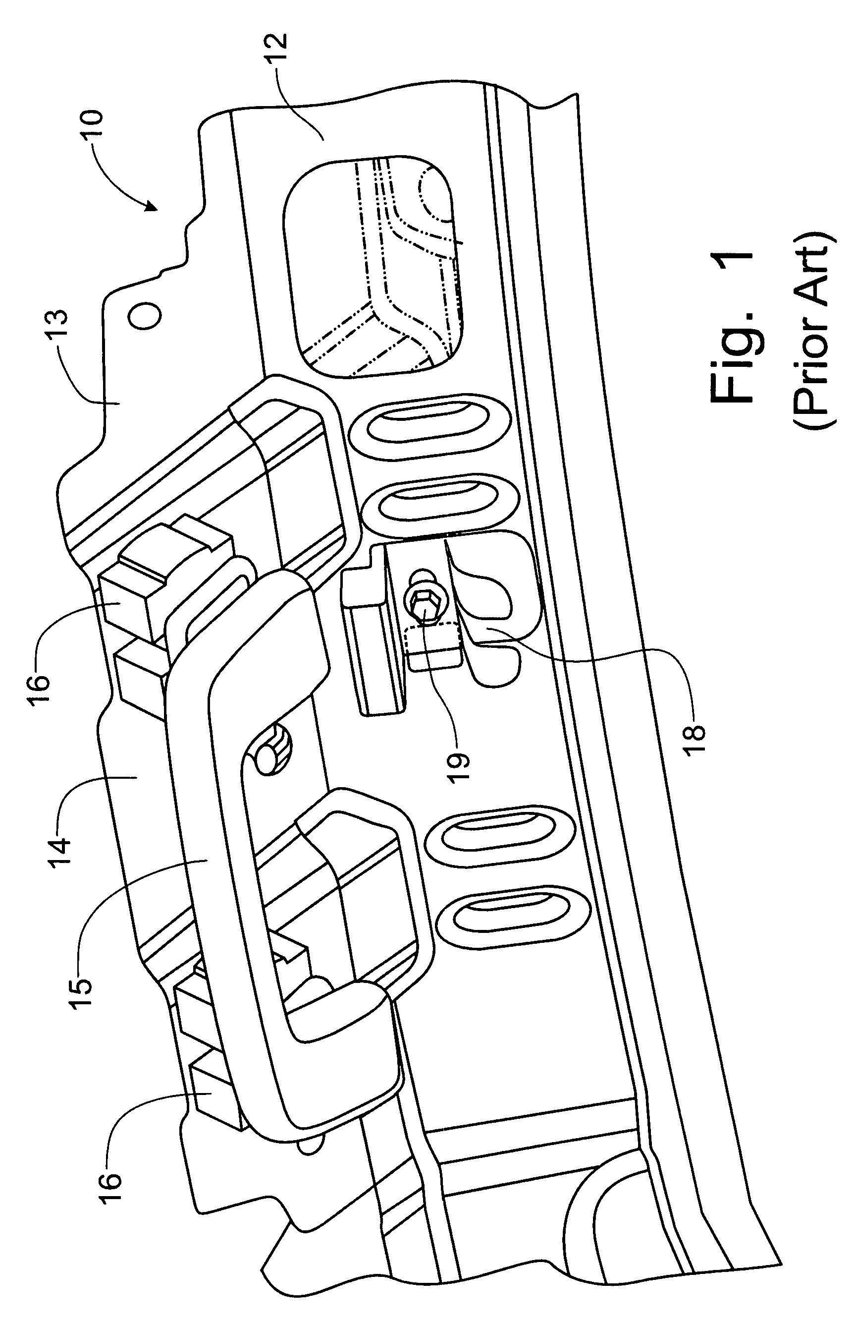
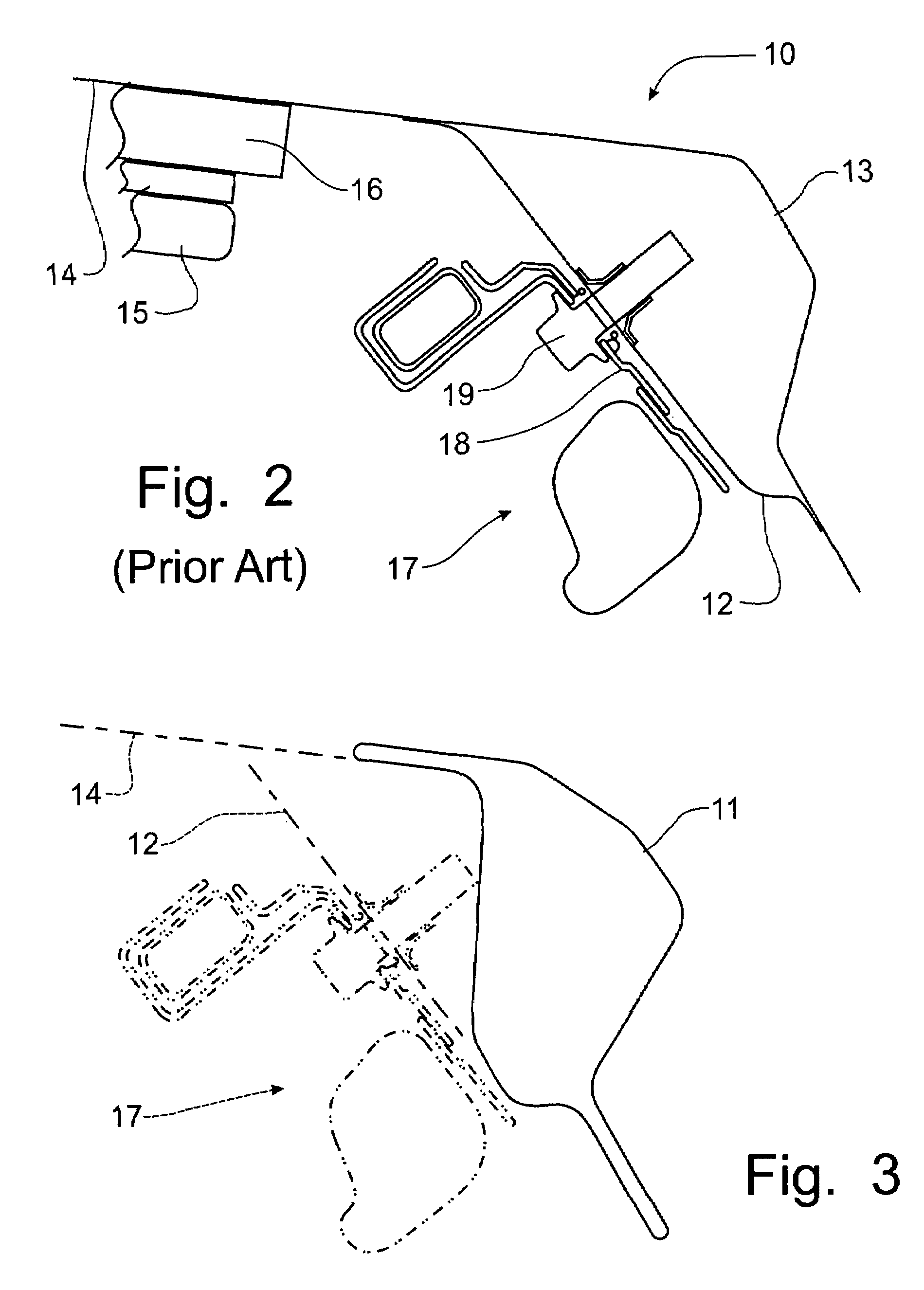
[0030]Referring to FIGS. 1 and 2, the mounting of a conventional grab handle and side curtain air bag attachment to a traditional stamped and welded automotive roof side rail, as is known in the art, can best be seen. This traditional automotive roof side rail 10 is formed from stamped inner and outer members, 12, 13, respectively, that are welded together to form the roof side rail. The outer member 13 projects upwardly past the inner member to provide a mounting surface 14 for the attachment of the connecting bracket 16 for the grab handle 15 thereto. The connecting bracket 18 for the side curtain air bag attachment 17 is attached directly to the inner member 12. The fastener 19 attaching the air bag connecting bracket 18 projects into the interior cavity of the roof side rail 10.

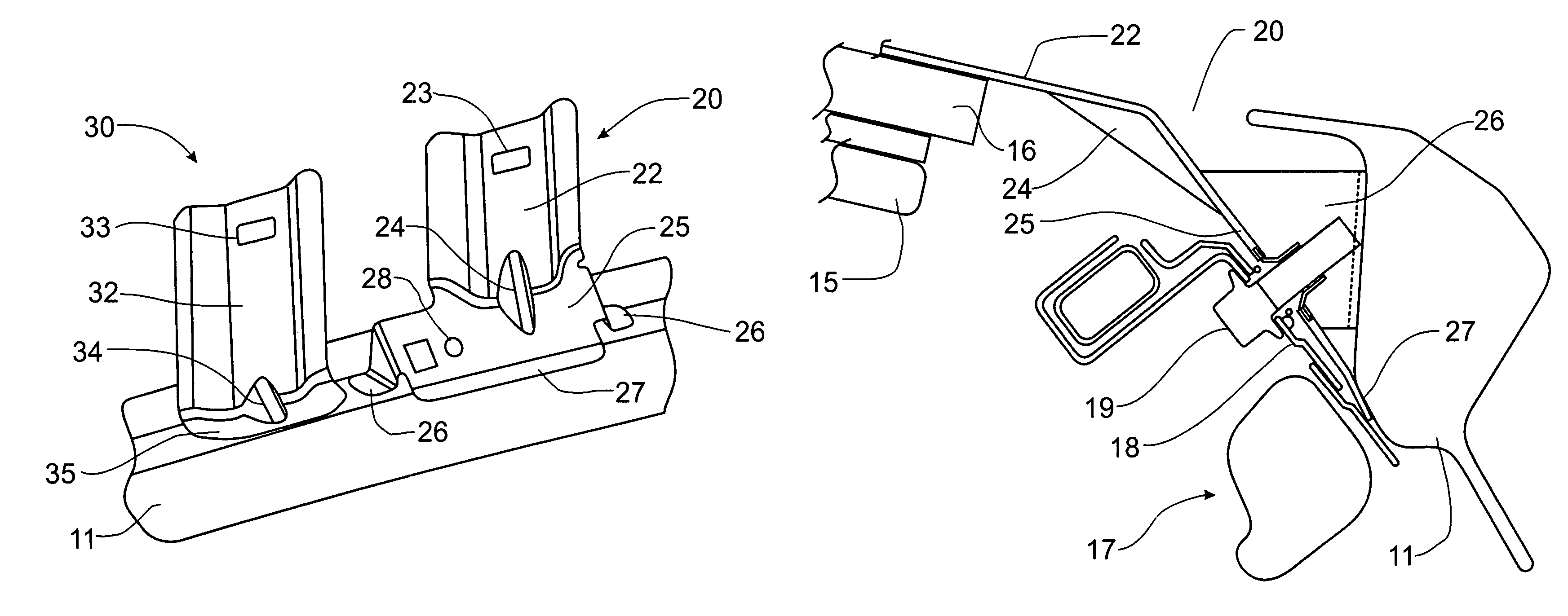
[0031]The utilization of the hydroforming manufacturing process to form a shaped automotive roof side rail 11, as depicted in FIG. 3, is limited in the ability to change shapes to accommodate issues such ...


PUM


Abstract

A dual function mounting bracket is affixed to a hydroformed roof side rail to allow the connecting brackets to be located at the same position as previously known despite the use of a hydroformed roof side rail frame member that has a substantially different shape and configuration. The dual function mounting bracket has a first mounting surface projecting upwardly from a second mounting surface to provide support for a grab handle connecting bracket. The second mounting surface provides support for the connecting bracket of a side curtain air bag. The second mounting surface is also configured with a pair of side tabs and a front tab for welding the mounting bracket to a hydroformed roof side rail. The grab handle spans between the mounting bracket and a spaced apart sole function mounting bracket. A bead between the first and second mounting surfaces on the dual function mounting bracket provides stiffness.

Description

FIELD OF THE INVENTION[0001]This invention relates generally to the mounting of a grab handle apparatus in an automotive vehicle and, more particularly, to a bracket that can be used with a hydroformed roof side rail to mount both the grab handle and the airbag attachment.BACKGROUND OF THE INVENTION[0002]Hydroformed tubular frame members are now being utilized in the production of automotive frames. The hydroforming process starts with a standard tubular stock member that is placed into a form or die shaped to correspond to the particular member to be formed. A liquid is then introduced into the interior of the tubular stock and pressurized until the tubular stock expands to assume the shape defined by the configured form. The expanded and re-shaped tubular stock now has a substantially different shape. By forming cutouts and other access openings into the re-shaped tubular member, spot-welding electrodes can gain access to opposing adjacent sides to create a weld bond between juxta...

Claims


Application Information

Patent Timeline
Patent Type & Authority Patents(United States)
IPC IPC(8): B60R21/20B60R21/213
CPCB60R21/213
Inventor CHEN, XIAOMINGWAGNER, DAVID A.FARUQUE, OMARGUIMBERTEAU, THIERRYSZALAY, DANIEL J.
Owner FORD GLOBAL TECH LLC
Why Eureka
Try Eureka