
Spread illuminating apparatus and display device incorporating same

a technology of illuminating apparatus and display device, which is applied in the direction of lighting and heating apparatus, planar/plate-like light guides, instruments, etc., can solve the problems of poor red spectral component, poor light emitted by the aforementioned b+y type, and not perfectly suited to video terminals, etc., and achieve excellent brightness distribution

Inactive Publication Date: 2010-02-16
MINEBEAMITSUMI INC
View PDF16 Cites 6 Cited by
  • Summary
  • Abstract
  • Description
  • Claims
  • Application Information

AI Technical Summary

Benefits of technology

The present invention provides a spread illuminating apparatus that can be used in various environments and achieve an excellent brightness distribution. The apparatus includes a light conductor plate and a light source unit with multiple white light sources that emit light with different light emission spectra. The light source unit can be controlled independently to turn on and off, allowing for optimal variation in illumination light according to different usage purposes and environments. This makes the apparatus ideal for use as a lighting means for a color LCD device in a mobile terminal.

Problems solved by technology

The light emitted by the aforementioned B+Y type LED, however, is poor in a red spectral component and therefore is not perfectly suited for a video terminal to show television movies or the like which requires high color rending properties.
The B+RX type LED, however, is inevitably deteriorated in visibility and conversion efficiency due to the increase of the red spectral component or achieves a smaller light beam than the B+Y type LED due to the increase of the fluorescent substance to absorb the blue light emitted from the semiconductor light emitting element.
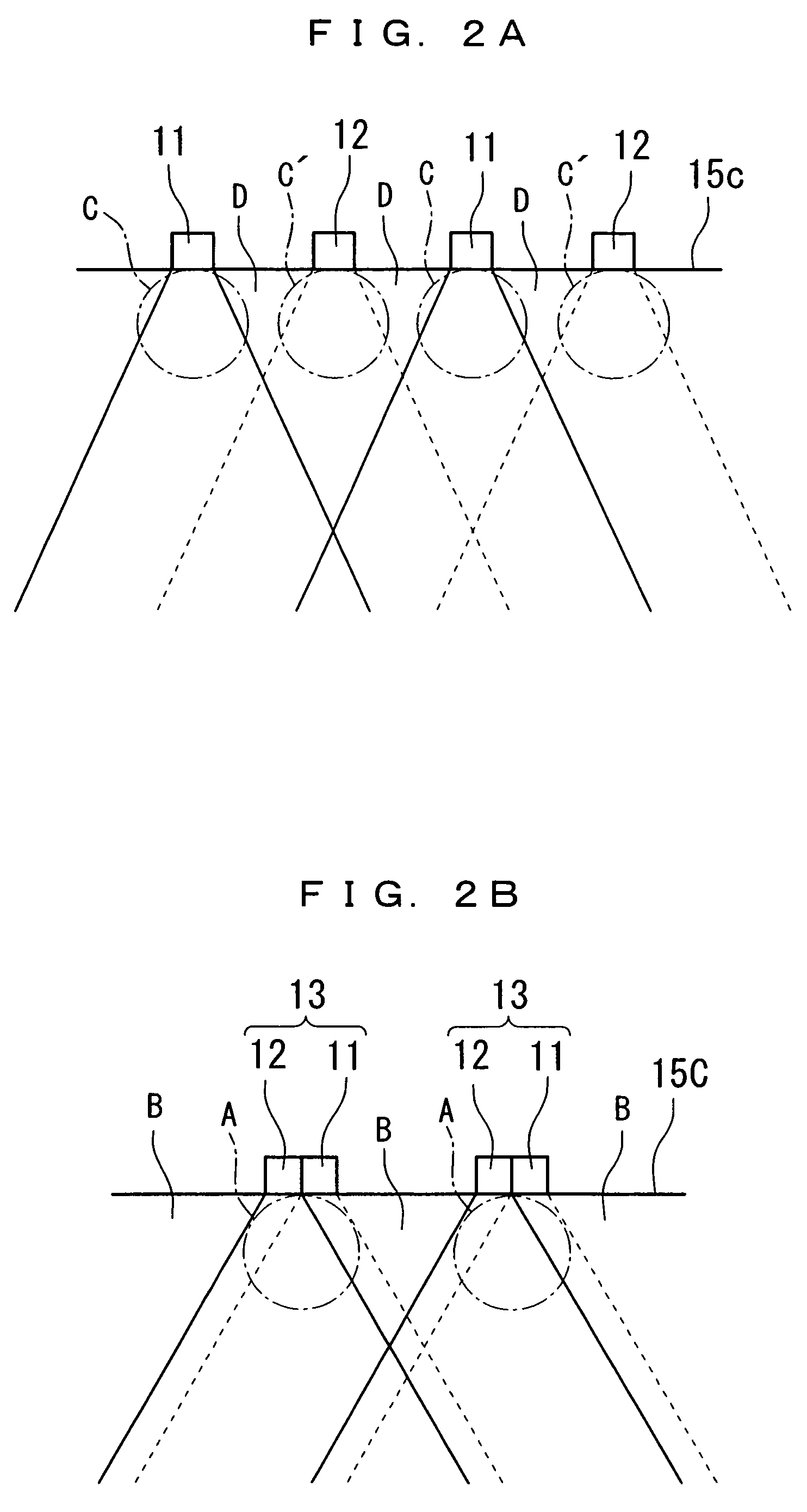
In the spread illuminating apparatus disclosed in, for example, the aforementioned Japanese Patent Application Laid-Open No. 2005-203326 where an illuminating light having specific properties is produced by simply turning on the different types of LEDs on a selective basis, it is difficult to achieve a decent brightness distribution across all lighting modes: specifically, the LEDs are all turned on at the same time, the LEDs are selectively turned on and off, and the like.

Method used


Image

  • Spread illuminating apparatus and display device incorporating same
  • Spread illuminating apparatus and display device incorporating same
  • Spread illuminating apparatus and display device incorporating same

Examples


Embodiment Construction

[0028]Exemplary embodiments of the present invention will hereinafter be described with reference to the accompanying drawings. It is to be noted that the drawings are provided for the purpose of explanation and may not accurately reflect actual configuration and dimension.

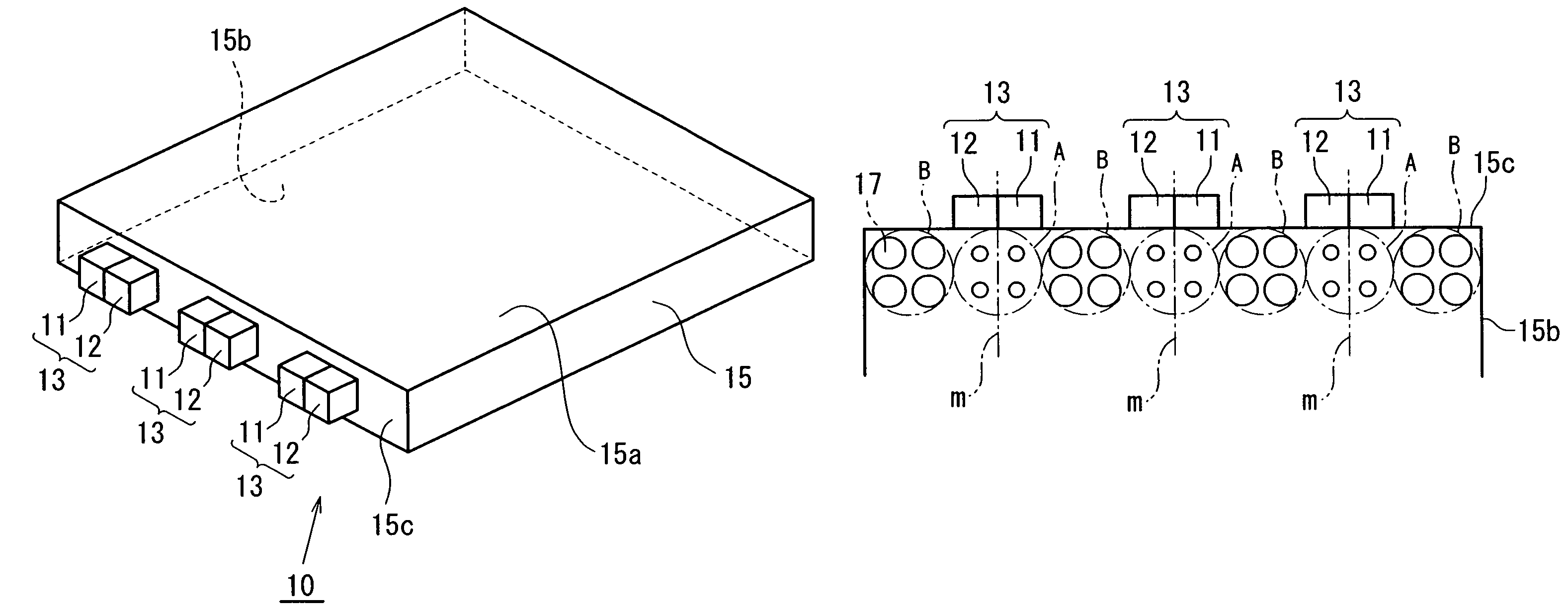
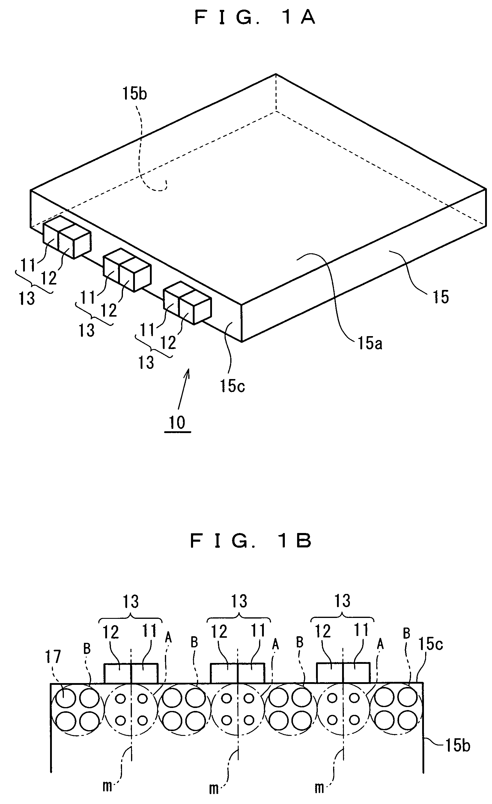
[0029]Referring to FIG. 1A, a spread illuminating apparatus 10 according to a first embodiment of the present invention generally includes a light conductor plate 15, and a plurality (three in the figure) of light source units 13 disposed at one side surface (light inlet surface) 15c of the light conductor plate 15.

[0030]The light conductor plate 15 is preferably produced such that a light transmissive resin, for example, polycarbonate resin is injection molded into a plate shape. Usually, an optical path converting means (not shown) to convert the direction of light is provided at one (lower side in the figure) major surface 15b (hereinafter, referred to as “lower major surface” as appropriate), whereby light int...


PUM


Abstract

A spread illuminating apparatus is provided which includes: a light conductor plate having a light inlet surface and two major surfaces; a light source unit disposed at the light inlet surface of the light conductor plate; and a light diffuser pattern disposed at the lower major surfaces of the two major surfaces of the light conductor plate, wherein the light source unit includes first and second white light sources which have respective different light emitting principles, are arranged in the width direction of the light conductor plate with their respective ends set close to one another, and which can be turned on and off independently of each other.

Description

BACKGROUND OF THE INVENTION[0001]1. Field of the Invention[0002]The present invention relates to a spread illuminating apparatus of side light type for use as a lighting means for a liquid crystal display device, and particularly to a spread illuminating apparatus suitable for use as a lighting means for a color liquid crystal display device for a compact mobile terminal, such as a mobile telephone.[0003]2. Description of the Related Art[0004]Currently, a spread illuminating apparatus of side light type in which a white light emitting diode (LED) as a primary light source is disposed at a side face (light inlet surface) of a light conductor plate is extensively used as a lighting means for a liquid crystal display (LCD) device with a relatively small display area for a compact mobile terminal, such as a mobile telephone. Such the white LED generally includes in combination a semiconductor light emitting element to emit a blue light and a fluorescent substance to absorb a blue light ...

Claims


Application Information

Patent Timeline
Patent Type & Authority Patents(United States)
IPC IPC(8): F21V7/04H01L33/50H01L33/54H01L33/56
CPCG02B6/0016G02B6/0068G02B6/0073G02F1/133615H04M1/22
Inventor EGAWA, MOTOJIEDAMITSU, TAKASHI
Owner MINEBEAMITSUMI INC
Learn More