
Human-powered flapping hydrofoil craft

a technology of hydrofoil and water craft, which is applied in the direction of marine propulsion, vessel construction, transportation and packaging, etc., can solve the problems of high degree of bobbing up and down, and achieve the effects of high power transfer, easy operation of controls, and convenient us

Inactive Publication Date: 2010-02-16
MARCH PHILIP A +3
View PDF4 Cites 22 Cited by
  • Summary
  • Abstract
  • Description
  • Claims
  • Application Information

AI Technical Summary

Benefits of technology

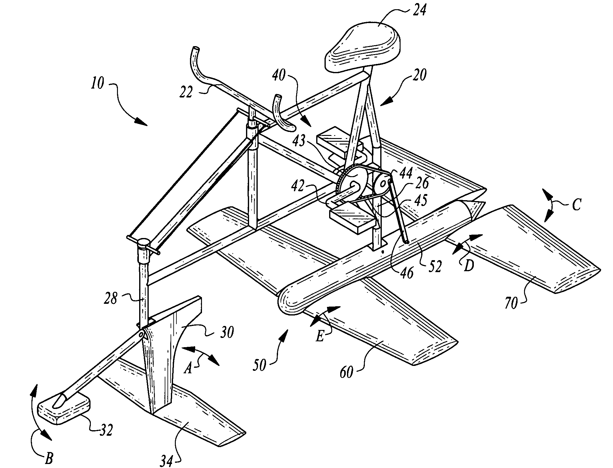
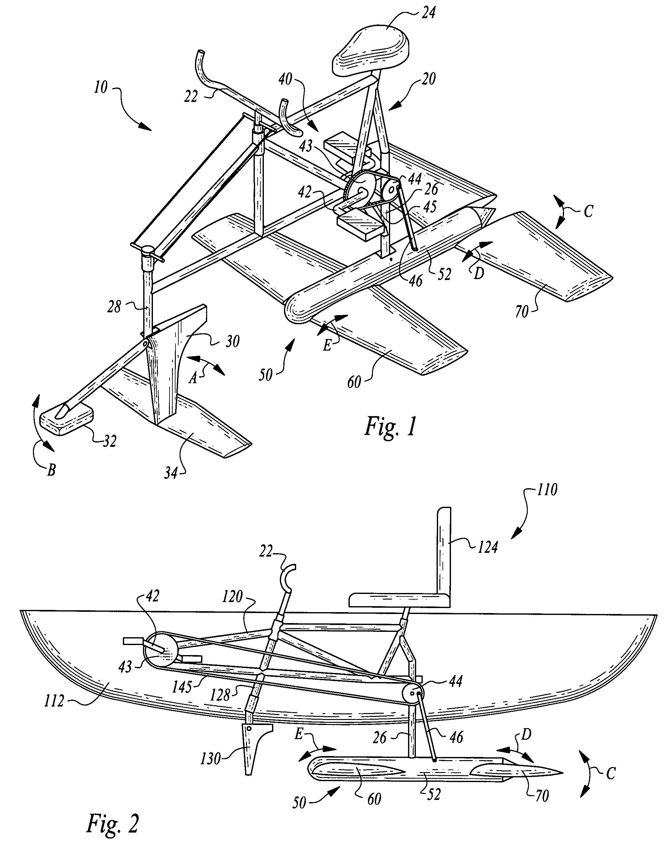
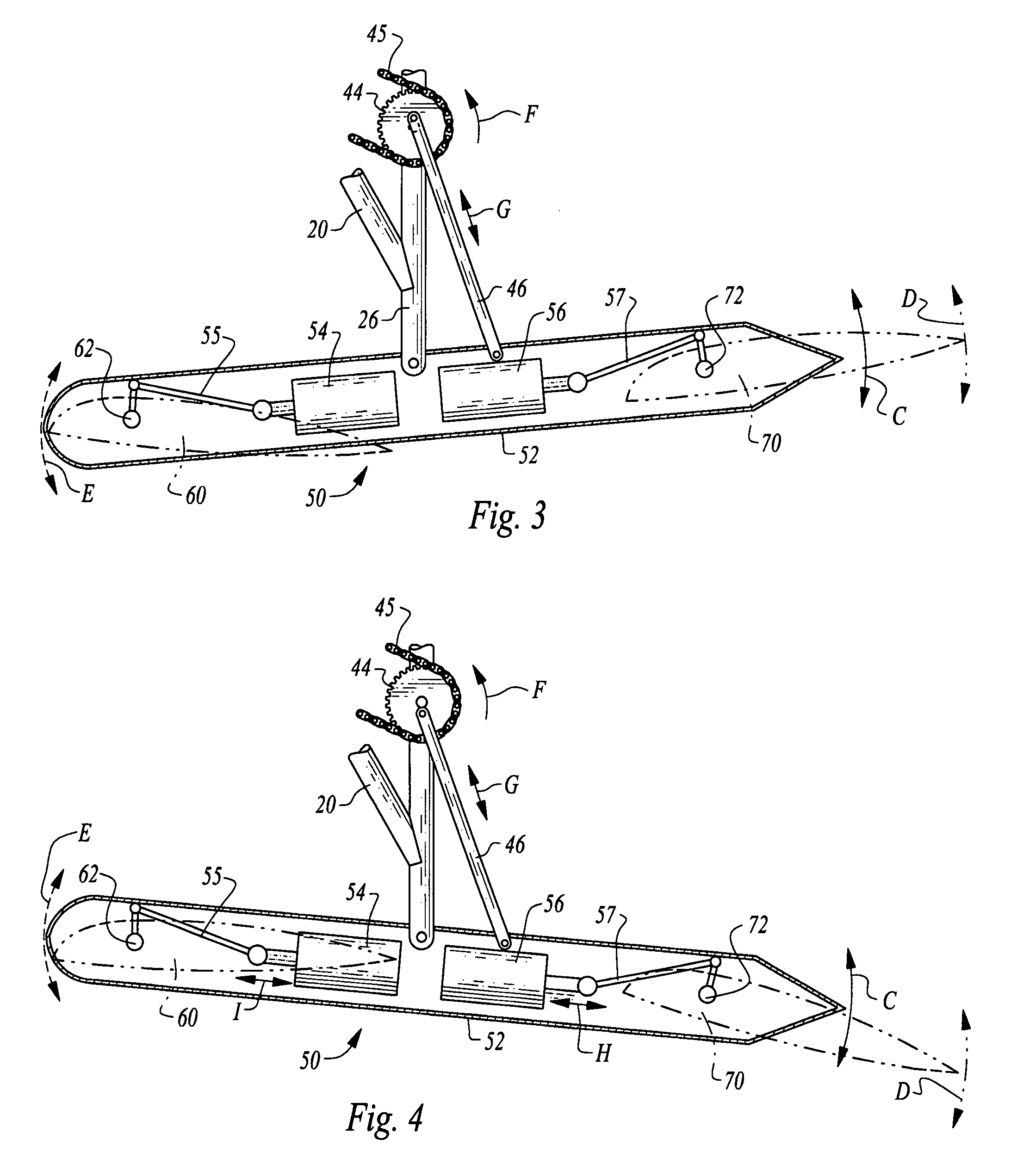
[0006]The nacelle is caused to oscillate in a heaving manner through action of a push rod coupled to the nacelle behind the mast and moving up and down. The push rod is driven by the power plant on the frame. In a preferred embodiment, the push rod is coupled eccentrically to a sprocket driven by a chain coupled to pedals on a crank shaft, so that the rider can also supply the power required to drive the water craft.
[0010]Accordingly, a primary object of the present invention is to provide a water craft which can successfully carry a rider over a water surface between an origin and a destination in a controlled fashion.
[0012]Another object of the present invention is to provide a water craft which can travel at relatively high speeds for a human powered water craft.
[0014]Another object of the present invention is to provide a water craft which can maintain balance and avoid excessive bobbing while still utilizing flapping foils for propulsion and lift.
[0016]Another object of the present invention is to provide a personal water craft which is easy to use with easy to operate controls and a high degree of power transfer from the user into propulsion of the craft.

Problems solved by technology

These prior art water craft are particularly characterized in a high degree of bobbing up and down as they move over the water.

Method used


Image

  • Human-powered flapping hydrofoil craft
  • Human-powered flapping hydrofoil craft
  • Human-powered flapping hydrofoil craft

Examples


Embodiment Construction

[0027]Referring to the drawings, wherein like reference numerals represent like parts throughout the various drawing figures, reference numeral 10 (FIG. 1) is directed to a water craft for conveying a human rider and potentially cargo over water. The water craft 10 utilizes a front foil 60 and rear foil 70 oscillating in a flapping motion to provide both propulsion and lift. Angles of attack for the foils 60, 70 are carefully controlled to optimize lift and propulsion to provide a smooth and efficient ride.

[0028]In essence, and with particular reference to FIG. 1, basic details of this invention are described, according to a preferred embodiment. The water craft 10 includes a frame 20 which is mostly oriented above a surface of the water. A steering fin 30 extends down from a forward portion of the frame 20 into the water for control of steering for the water craft 10. A power plant 40 is coupled to the frame 20 and outputs power for generation of propulsion and lift to carry the wa...


PUM


Abstract

A pair of foils are pivotably coupled to a nacelle. The nacelle is pivotably coupled to a mast extending down from to a frame and below a water surface. A push rod oscillates, causing the nacelle to experience a heaving motion, in turn causing the foils to flap up and down. The push rod is driven by a power plant such as a human rider. Angles of attack for the foils are actively controlled to optimize lift and propulsion forces provided by the foils to cause the water craft to move over the water. A steering fin is also provided for heading control of the water craft. A control system for separate angles of attack for the foil sends appropriate information to servo motors which cause the foils to rotate relative to the nacelle to achieve optimal angles of attack relative to the particular position of the nacelle at any given moment.

Description

CROSS-REFERENCE TO RELATED APPLICATIONS[0001]This application claims benefit under Title 35, United States Code § 119(e) of U.S. Provisional Application No. 60 / 858,766 filed on Nov. 14, 2006 and U.S. Provisional Application No. 60 / 860,025 filed on Nov. 20, 2006.FIELD OF THE INVENTION[0002]The following invention relates to hydrofoil water craft which utilize submerged foils to carry a weight of the vehicle over a surface of the water without substantial contact with the surface. More particularly, this invention relates to hydrofoil water craft which include foils which flap up and down to both provide lift and propulsion for the vehicle.BACKGROUND OF THE INVENTION[0003]Flapping foil hydrofoil water craft are known in the prior art. Exemplary of such flapping foil hydrofoil water craft are the devices disclosed in U.S. Pat. No. 7,021,232 and U.S. Pat. No. 6,099,369. These prior art devices are generally characterized by including a foil which moves up and down with an angle of attac...

Claims


Application Information

Patent Timeline
IPC IPC(8): B63H1/36
CPCB63H1/36B63H16/12B63H2016/005B63H2016/202B63B1/246B63B1/285B63H1/30B63H1/37B63H2016/085
Inventor MARCH, PHILIP A.RIDGELY, JOHN R.GIBSON, SHERWOOD P.MARCH, PETER R.
Owner MARCH PHILIP A
Learn More