Wire connection structure for laminated glass and laminated glass including such a wire connection structure

a technology of laminated glass and wire connection structure, which is applied in the direction of coupling device connection, non-linear optics, instruments, etc., can solve the problems of reducing the quality of laminated glass, and reducing the use of lead-containing solder. , to achieve the effect of stable electrostatic-capacitive coupling, simple structure and simplified production process

Active Publication Date: 2010-02-16
AGC INC
View PDF9 Cites 22 Cited by
  • Summary
  • Abstract
  • Description
  • Claims
  • Application Information

AI Technical Summary

Benefits of technology

[0016]The present invention as stated above offers the following effects. When the housing is disposed on laminated glass, followed by simply inserting the terminal, the external electrode can be pressed against the laminated glass by the elasticity of the terminal, with the result that it is possible to obtain stable electrostatic-capacitive coupling.
[0017]Since it is not necessary to print silver paste on the laminated glass and bake the printed paste for formation of the external electrode, it is possible to simplify the production process. Further, since the number of required parts is small and since the structure is simple, it is possible to simplify the production and to reduce the cost.
[0018]Further, since the conductor embedded in the laminated glass is electrically connected to the external electrode without use of solder, it is not necessary to take disposal of solder into account. Thus, the present invention contributes to restrain the cost of disposal. The present invention can prevent the strength of glass from being lowered by the thermal shock caused by soldering. The present invention can improve the appearance of the wire connection structure since the terminal is prevented from being exposed as in a case where the terminal is soldered.
[0019]Further, it is easy to adopt a shape complying with the standard prescribed in each country (such as, Japanese Industrial Standards in Japan) as the shape of the terminal strip of the terminal. Thus, it is possible to utilize a standardized connector, which has been used as a connector on the side of a lead wire. As a result, it is not necessary to procure new parts. Further, it is easy to repair parts.

Problems solved by technology

In the above-mentioned conventional wire connection structure, since the heat generated during the soldering operation causes thermal stress in the laminated glass 51, there is a fear that the quality of the laminated glass is lowered.
Further, since the solder used for a window glass for automobiles usually contains lead, much work is needed in treating the solder containing lead at the time of disposing the glass.
Further, since regulations to the use of lead-containing solder, such as the ELV (End Life of Vehicle) directive and the WEEE & RoHS (Waste Electrical and Electronic Equipment & Restriction of the use of certain Hazardous Substances in electrical and electronic equipment) directive set by the European Union, have started to be considered in many countries, it might be impossible in the future to use lead-containing solder.

Method used


Image

  • Wire connection structure for laminated glass and laminated glass including such a wire connection structure
  • Wire connection structure for laminated glass and laminated glass including such a wire connection structure
  • Wire connection structure for laminated glass and laminated glass including such a wire connection structure

Examples


Embodiment Construction

[0048]Now, embodiments of the present invention will be described in reference to the accompanying drawings.

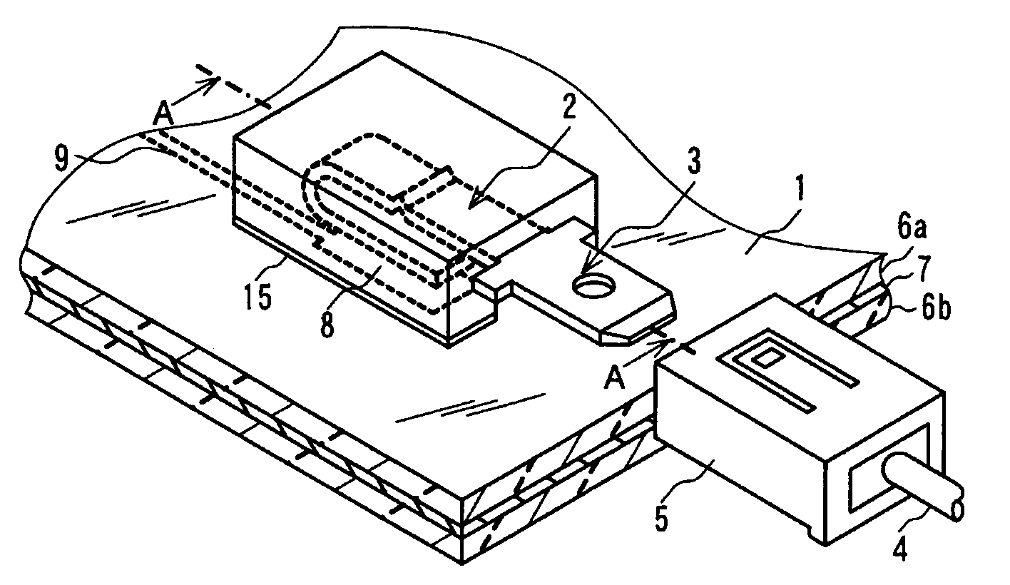
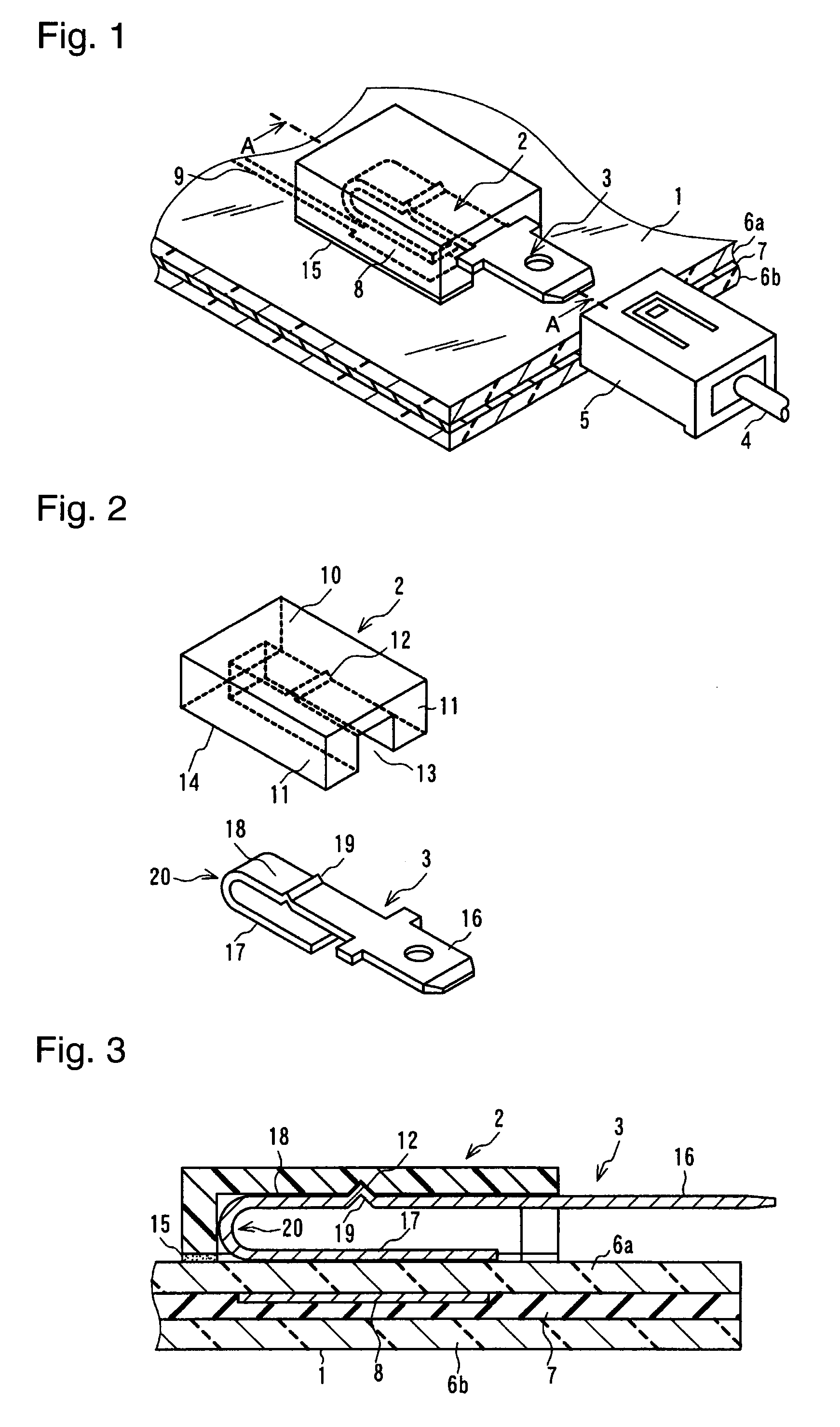
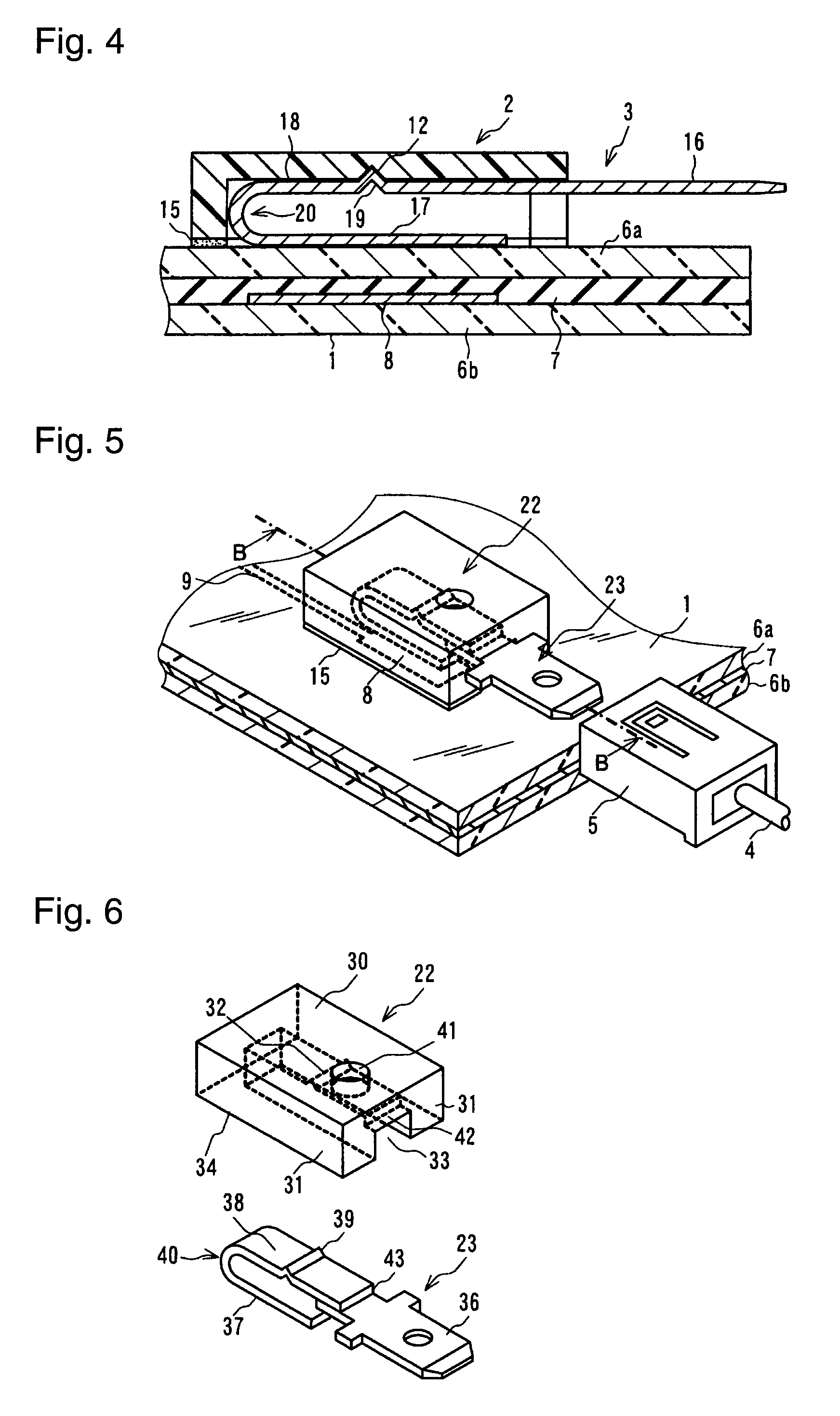
[0049]FIG. 1 is a perspective view showing an embodiment of the present invention. FIG. 2 is an exploded perspective view of a housing and a terminal. FIG. 3 is a cross-sectional view taking along line A-A of FIG. 1. FIG. 4 is a cross-sectional view showing another embodiment, which is different from the embodiment of FIG. 1 in that an embedded electrode is located at a different position. Each of the embodiments of the present invention comprises laminated glass 1, a housing 2, a terminal 3 and a connector 5, which is located on the side of a lead wire 4 connected to an external instrument. The laminated glass 1 shown in FIG. 1 and FIG. 3 comprises two glass sheets 6a and 6b bonded together through an intermediate film 7 made of, e.g., polyvinyl butyral, and an electrode (hereinbelow, referred to as the “embedded electrode 8”) disposed between the two glass sheets 6a and 6b. ...


PUM


Abstract

There is provided a wire connection structure for laminated glass, which is capable of electrically connecting a conductor embedded in laminated glass and a lead wire without soldering, and laminated glass including such a wire connection structure.A wire connection structure comprising an embedded electrode 8 embedded in laminated glass 1; a housing 2, 22 configured to form a space along with the laminated glass 1 and to have an insertion slot 13, 33 formed therein so as to communicate with the space, the housing being disposed on the laminated glass 1 so that the space confronts the embedded electrode 8; an elastic terminal 3, 23 received into the space of the housing 2, 22 and made of a conductive material; and a connector 5 connected to a lead wire 4; the terminal 3, 23 including a terminal strip 16, 36 to be detachably connected to the connector 5, and an external electrode 17, 37, the external electrode being configured to be electrostatic-capacitively coupled with the embedded electrode 8 when the terminal is received into the housing 2, 22 and is elastically deformed in the space to be pressed against the laminated glass.

Description

TECHNICAL FIELD[0001]The present invention relates to a wire connection structure for laminated glass, which connects, through electrostatic-capacitive coupling, an embedded electrode embedded in laminated glass and an external electrode to be connected to a lead wire, and laminated glass including such a wire connection structure.BACKGROUND ART[0002]There has been known a glass antenna, which adds an antenna function of receiving, e.g., AM, FM or TV waves to a window glass for automobiles by forming an antenna conductor in an antenna pattern for reception of electromagnetic waves in the window glass. Such a glass antenna is formed in a fixed window, such as a front windshield comprising laminated glass, or a rear windshield or a side windshield comprising tempered glass.[0003]Laminated glass is prepared by bonding a plurality of glass sheets through an intermediate film. The antenna pattern is formed by, e.g., sealing an antenna conductor and an electrode connected to one end of th...

Claims


Application Information

Patent Timeline
Patent Type & Authority Patents(United States)
IPC IPC(8): H01Q1/32H01R13/62
CPCB32B17/10036B32B17/10293B32B17/10376H01R13/428H01R13/04H01R2201/02H01R2201/26
Inventor HISAEDA, KATSUMI
Owner AGC INC
Why Eureka
Try Eureka