Remote location VOIP roaming behind firewalls

a firewall and remote location technology, applied in the field of ip telephony, can solve the problems of slow deployment of ip telephony, limited provision for roaming ip telephony devices within a network or network, and inability to be particularly widespread

Inactive Publication Date: 2010-02-16
SBC KNOWLEDGE VENTURES LP
View PDF19 Cites 54 Cited by
  • Summary
  • Abstract
  • Description
  • Claims
  • Application Information

AI Technical Summary

Problems solved by technology

Deployment of IP telephony has been slow and thus far, not particularly widespread because of compatibility issues with firewalls and network address translators (NAT).
Provisions for roaming IP telephony devices within a network or networks have been limited, as most organizations, from large corporations to small businesses, employ the use of these network devices.
Thus, users residing in these networks are often precluded from fully utilizing and benefiting from IP telephony.
Networks protected by firewalls that allow persistent, un-monitored channels become highly vulnerable since an unmonitored channel makes the network susceptible to inbound, unfiltered, malicious traffic.
Additional complications arise due to the fact that IP telephony solutions for networks having NAT require the discovery of NAT translations.
This achieves less than optimal performance, since an additional piece of software must discover compression and de-compression techniques as well as NAT translations to allow for the discovery of prematurely closed telephony connections through the firewall.
This method does not guarantee that a terminal device will receive the call placed by the calling user.
It does not provide for the network appliance to obtain configuration information from a plurality of remote configuration sources.
This method fails to provide communication privileges with the destination node in the event the user identifier is unknown, even if the network address is unknown.

Method used


Image

  • Remote location VOIP roaming behind firewalls
  • Remote location VOIP roaming behind firewalls
  • Remote location VOIP roaming behind firewalls

Examples


Embodiment Construction

[0019]While this invention is illustrated and described in a preferred embodiment, the invention may be produced in many different configurations. There is depicted in the drawings, and will herein be described in detail, a preferred embodiment of the invention, with the understanding that the present disclosure is to be considered an exemplification of the principles of the invention and the associated functional specifications for its construction and is not intended to limit the invention to the embodiment illustrated. Those skilled in the art will envision many other possible variations within the scope of the present invention.

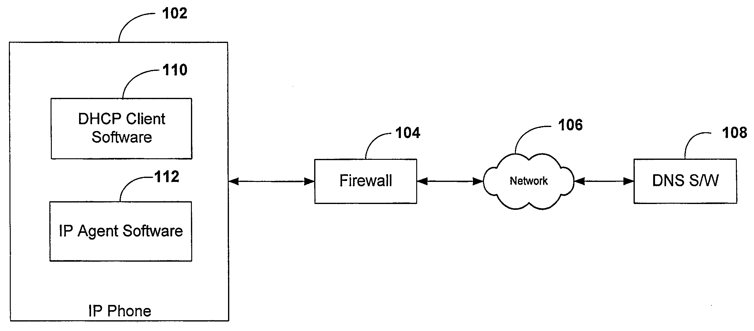
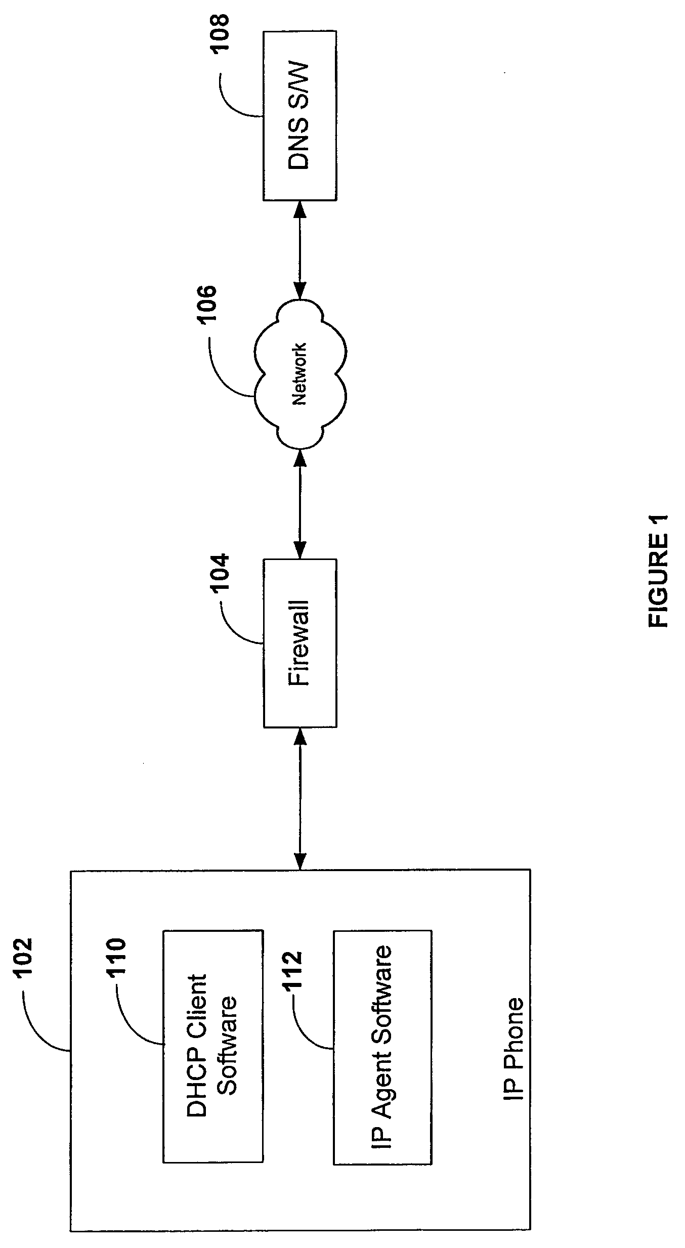
[0020]FIG. 1 illustrates an overview of the present invention system for facilitating communication between an IP phone 102 behind firewall 104 and a dynamic DNS switch 108 over a network 106. The IP phone of the present invention comprises DHCP client software 110 and IP agent software 112. Network 106 is any of, but is not limited to, the following netw...


PUM


Abstract

A connection between an external host and a host internal to a network (e.g., VPN or LAN) and located behind a firewall and / or NAT-enabled device is established and maintained. A dynamic DNS server is updated with the remote location (RL) information associated with the internal host. This information includes the dialed number (i.e. the number assigned to the internal host), the physical address of the internal host, the private IP address corresponding to the internal host, the public IP address corresponding to the firewall, and the port on which voice data is to be communicated. Each time the internal host's location changes, a new and updated record is sent to the dynamic DNS server. The call placed by an external host reaches its final destination based on the record information in the DNS server table. Once the connection between the external host and the internal host is established, voice traffic is “cut-through” the firewall on this channel associate with the port designated by the RL record.

Description

BACKGROUND OF INVENTION[0001]1. Field of the Invention[0002]The present invention relates generally to the field of IP telephony. More specifically, the present invention is related to IP telephony behind firewalls.[0003]2. Discussion of Prior Art[0004]Deployment of IP telephony has been slow and thus far, not particularly widespread because of compatibility issues with firewalls and network address translators (NAT). Provisions for roaming IP telephony devices within a network or networks have been limited, as most organizations, from large corporations to small businesses, employ the use of these network devices. Thus, users residing in these networks are often precluded from fully utilizing and benefiting from IP telephony. Networks protected by firewalls that allow persistent, un-monitored channels become highly vulnerable since an unmonitored channel makes the network susceptible to inbound, unfiltered, malicious traffic. Additional complications arise due to the fact that IP t...

Claims


Application Information

Patent Timeline
Patent Type & Authority Patents(United States)
IPC IPC(8): H04L12/66H04L12/56H04L29/06H04L29/12H04M7/00
CPCH04L29/06027H04L29/12066H04L29/12094H04L29/12301H04L29/12547H04L61/1511H04L61/1529H04L61/2076H04L61/2582H04L63/029H04M7/006H04L65/1069H04L65/1006H04L61/4535H04L61/4511H04L61/5076H04L65/1104H04L65/1101
Inventor DOHERTY, JAMES M.ADAMS, THOMAS LEEMUELLER, STEVE
Owner SBC KNOWLEDGE VENTURES LP
Why Eureka
Try Eureka