Pulse generator and the transmitter with a pulse generator

a pulse generator and transmitter technology, applied in pulse train generators, pulse techniques, baseband system details, etc., can solve the problems of increasing power consumption, affecting so as to reduce the effect of reducing the accuracy of output signal waveforms

Active Publication Date: 2010-02-16
RENESAS ELECTRONICS CORP
View PDF8 Cites 8 Cited by
  • Summary
  • Abstract
  • Description
  • Claims
  • Application Information

AI Technical Summary

Benefits of technology

[0006]In the UWB system, since transmitted power is spread in a wideband, it is considered that its interference against other wireless device is slight. Moreover, since a wideband is used, a transmission speed is also fast.
[0007]In the UWB system, there exist the DS (Direct Spread) system, the MB-OFDM (Multi Band-Orthogonal Frequency Division Multiplexing) system, and the IR (Impulse Radio) system. Although the DS system and the MB-OFDM system feature fast transmission speed, high-speed operations are required; therefore, power consumption tends to increase. On the other hand, the IR system is slow in communication speed compared with the DS system and the MB-OFDM system, it transmits power intermittently. Therefore, it is a system that realizes lower power consumption and enables simplification of a circuit configuration. Accordingly, the UWB-IR system is promising in the ubiquitous society that aims at communication between devices, such as a wireless information device, that are required to be of lower power consumption.
[0011]The object of this invention is to provide a pulse generator for UWB transmission that solves problems of simplification of configuration, lower power consumption, and suppression of LO leakage, and a transmitter that uses it.

Problems solved by technology

In the UWB system, since transmitted power is spread in a wideband, it is considered that its interference against other wireless device is slight.
Moreover, since a wideband is used, a transmission speed is also fast.
Although the DS system and the MB-OFDM system feature fast transmission speed, high-speed operations are required; therefore, power consumption tends to increase.
On the other hand, the IR system is slow in communication speed compared with the DS system and the MB-OFDM system, it transmits power intermittently.
Since the conventionally proposed pulse generator of the UWB-IR system requires a high voltage of about a few tens of volts and uses delay lines, it has problems: because delay lines are used, accuracy is low in an LSI (Large Scale Integrated Circuits), and it is difficult to realize an LSI using general purpose processes.

Method used


Image

  • Pulse generator and the transmitter with a pulse generator
  • Pulse generator and the transmitter with a pulse generator
  • Pulse generator and the transmitter with a pulse generator

Examples


first embodiment

[0055]FIG. 4 shows details of the delay circuit 105 of a pulse generator that is a first embodiment of this invention. The delay circuit 105 consists of a plurality of delay elements provided in series, and has a function of delaying an inputted signal over a plurality of stages, each stage delaying the signal by a delay time Td. In the following example, an example whose delay circuits are of nine stages is shown.

[0056]In order to improve the accuracy of delay, it is preferable for the delay circuit 105 to adopt a DDL (Delay Locked Loop) consisting of: a delay array 6010 composed of delay elements 601 each of which is capable of controlling a delay time, such as an inverter, being connected to one another and arranged in a plurality of stages; a phase comparator (PD) 6012 that compares phases between the input clock and an output of the last-stage delay element and generates a square wave having a pulse width equal to a time of the phase difference; and a charge pump (CP) 6014 for ...

second embodiment

[0083]A second embodiment of this invention will be described using FIGS. 13-16. In the second embodiment, the first embodiment shown in FIG. 1 is altered so as to have a differential configuration, and the load of the amplitude control unit is altered to a combination of a resistor and a capacitor.

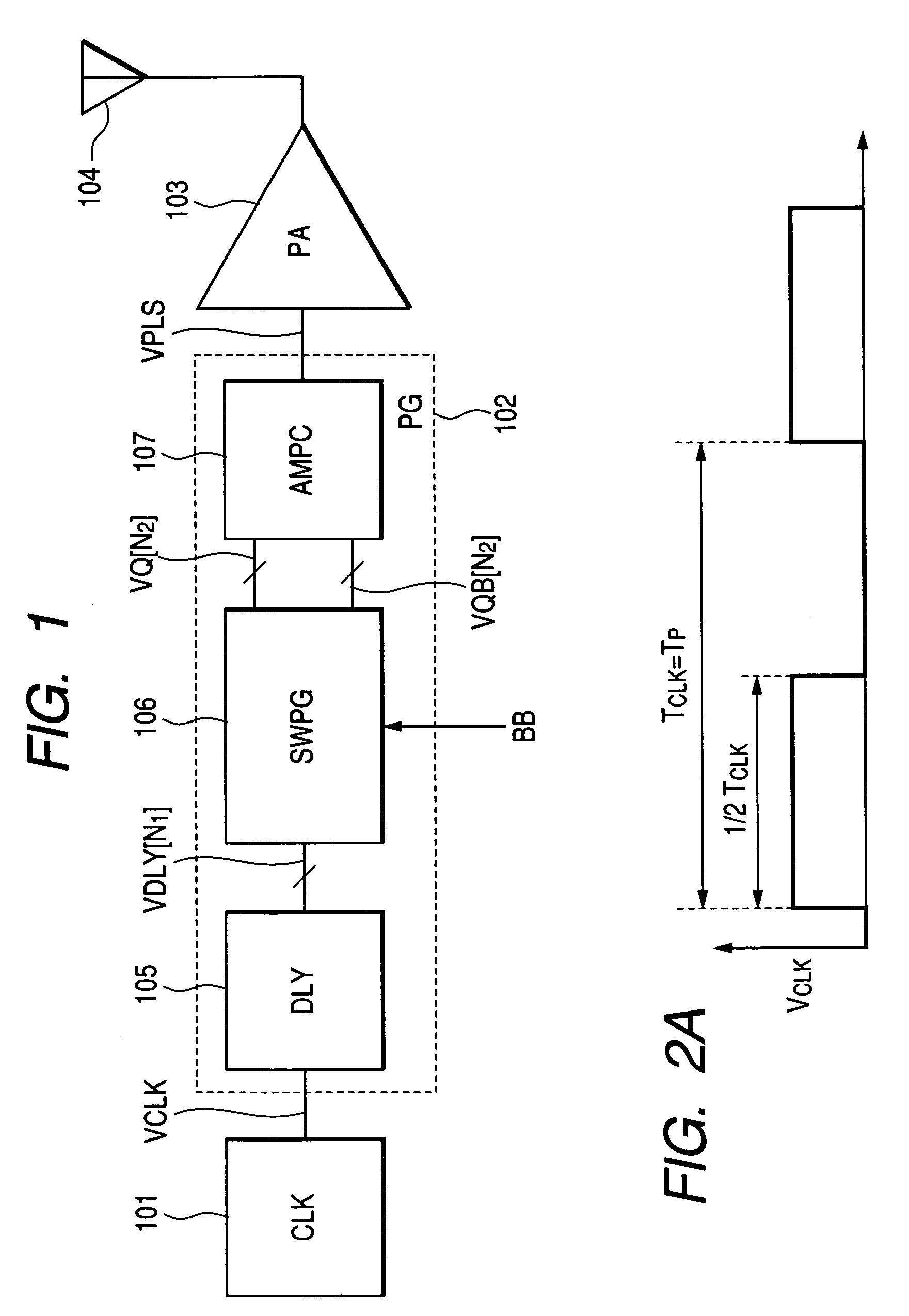
[0084]As shown in FIG. 13, a pulse generator is constructed with the delay circuit 105 for generating a plurality of signals having different delay times, two square-wave pulse generation circuits 1106 each of which controls an output pattern of a plurality of square wave pulses each having a pulse width comparable to its differential delay based on the baseband signal (BB) and outputs the pulses; and the amplitude control unit 107 for generating waveforms whose amplitudes are different depending on an input of the square wave pulse. A transmitter is constructed with the clock generator 101, the pulse generator 102, the power amplifier (PA) 103, and the antenna 104.

[0085]Next, a concrete ...

third embodiment

[0096]A third embodiment is an example in which the current sources in the amplitude control unit in the first embodiment are altered to voltage sources.

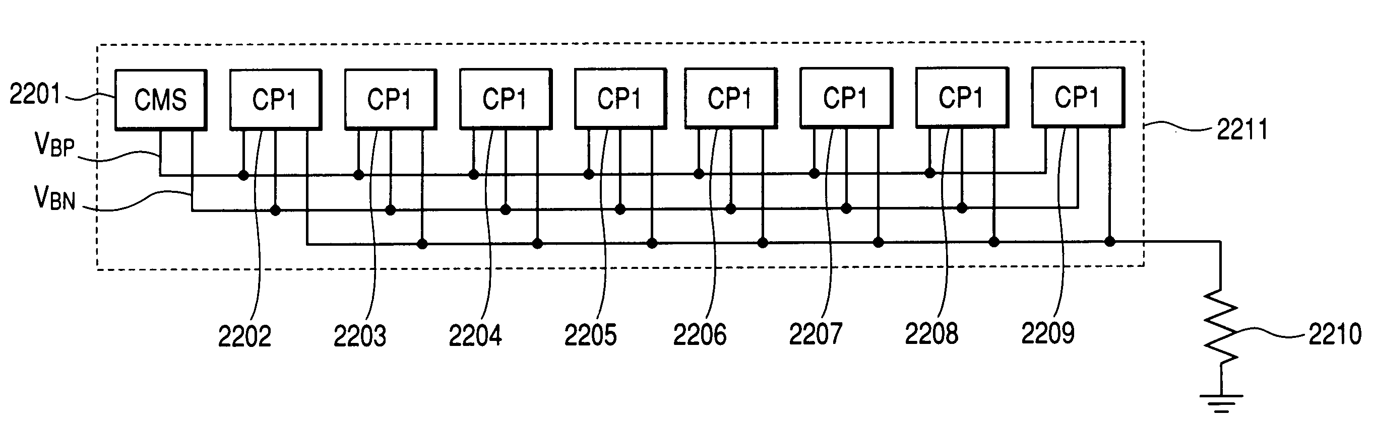
[0097]FIG. 17 shows a pulse generator according to a third embodiment this invention. The pulse generator of FIG. 17 is the amplitude alteration unit of the first embodiment shown in FIG. 4 whose current source is altered to a voltage source. As shown in FIG. 17, the pulse generator consist of the clock generator 101, the delay circuit 105, a square-wave pulse generation circuit 1506, and an amplitude control unit 1507 made up of voltage sources 1002 and MOS switches 1001. In the following example, an example whose delay circuits are of six stages is shown.

[0098]An output of the clock generator 101 is fed to the delay circuit 105, an output of the delay circuit 105 and the baseband signal are fed to the square-wave pulse generation circuit 1506, an output of the square-wave pulse generation circuit 1506 is fed to the amplitude contr...


PUM


Abstract

A pulse generator for UWB transmission, lower power consumption, and suppression of LO leakage by nonuse of the LO signal. The pulse generator includes a clock generator (CLK) for giving clock of a predetermined period; a delay circuit (DLY) equipped with a function of controlling a delay time and for delaying the clock; a square-wave pulse generation circuit (SWPG) that receives information being spread by a spread code and modulates phases of square wave pulses that have a pulse width corresponding to a differential delay for one stage of the delay circuit; and an amplitude control unit (AMPC) that outputs an impulse sequence having the pulse width of the square wave in a predetermined amplitude and combines the impulses; and outputs pulses that have a predetermined envelope form.

Description

CLAIM OF PRIORITY[0001]The present application claims priority from Japanese application JP 2005-042031 filed on Feb. 18, 2005, the content of which is hereby incorporated by reference into this application.FIELD OF THE INVENTION[0002]This invention relates to a pulse generator for ultra wideband transmission that generates a waveform pulse for impulse radio communications, and a transmitter that uses it.BACKGROUND OF THE INVENTION[0003]Regarding the UWB-IR system, JP-A No. 241860 / 2004 and JP-A No. 241859 / 2004 disclose a pulse generator that is configured to obtain a pulse signal for transmission by synthesizing a mixer output of a signal of a local oscillator and a Gaussian pulse using the local oscillator and the mixer. Moreover, JP-A No. 241860 / 2004 also discloses a technique of generating a pulse shaped signal of a low frequency by assigning weights to output signals of a plurality of current sources.[0004]Moreover, JP-A No. 535552 / 2003 discloses a transmitter that transmits inf...

Claims


Application Information

Patent Timeline
Patent Type & Authority Patents(United States)
IPC IPC(8): H04B1/00H03K3/64H03K3/80H04B1/717H04J13/00H04L25/49
CPCH04B1/7174H04L25/03834
Inventor NORIMATSU, TAKAYASUFUJIWARA, RYOSUKEKOKUBO, MASARUMAEKI, AKIRA
Owner RENESAS ELECTRONICS CORP
Why Eureka
Try Eureka