Waveguide-type broadband optical isolator

a broadband optical isolator and waveguide technology, applied in the direction of optical waveguide light guide, optical light guide, instruments, etc., can solve the problems of unintentional behavior, degrade the oscillation characteristics of semiconductor lasers, and degrade the operation characteristics of devices

Inactive Publication Date: 2010-02-16
MITSUMI ELECTRIC CO LTD
View PDF11 Cites 6 Cited by
  • Summary
  • Abstract
  • Description
  • Claims
  • Application Information

AI Technical Summary

Benefits of technology

[0028]The present invention has been developed in view of the above-described circumstances. An object of the present invention is to provide a waveguide-type broadband optical isolator which has a broadened usable operating wavelength range with a wavelength-dependence of backward propagating waves reduced, and operates also on two wavelengths of a 1.31-μm band and a 1.55-μm band for use in long-distance optical fiber communications.

Problems solved by technology

If the optical isolator is not placed on the exit end of the semiconductor laser, a reflected return light is incident on the semiconductor laser and degrades the oscillation characteristics of the semiconductor laser.
Not only in the above-described semiconductor laser, but also in optical active devices such as an optical amplifier, the incidence of an unintentional backward light degrades the operation characteristics of the device and may also cause some unintentional behavior.
In other words, errors resulting from the design conditions, wherein interference optical paths are in-phase for the forward propagating waves and are in phase opposition for the backward propagating waves, occur, thereby to degrade the characteristics of the isolator.
This shows that when the difference between the operating wavelength and the designed wavelength increases, the degradation of the oscillation characteristics of a laser caused by insufficient suppression of the backward propagating waves, rather than by a diffusion loss of an incident light, significantly increases.
When the operating wavelength is not within that range, the backward propagating wave's diffusion effect on the waveguide-type optical isolator does not deliver a performance which satisfies the requirements.
As a result, since the wavelength-dependence of the isolation ratio defined by “backward loss−forward loss” is approximately determined by the wavelength-dependence of the backward loss, a conventional waveguide-type optical isolator cannot deliver the performance when the operating wavelength deviates from the wavelength range of 1.54 to 1.56 [μm].
In Non-Patent Documents 1 and 2, the obtained isolation characteristic is 4.9 [dB], which is insufficient for practical devices.
As a result, a problem arises in that the nonreciprocal phase shifter increases in length by nearly 7.5 times.
Although Non-Patent Document 4 is significant in that the nonreciprocal phase shift effect as a physical phenomenon is experimentally verified, it does not provide or describe an actual device such as an optical isolator.

Method used


Image

  • Waveguide-type broadband optical isolator
  • Waveguide-type broadband optical isolator
  • Waveguide-type broadband optical isolator

Examples


embodiment-1

[0089]Band broadening in a waveguide-type optical isolator having a waveguide layer comprising the magneto-optical material Ce:YIG (CeY2Fe5O12) shown in FIG. 19 will now be described as Embodiment-1.

[0090]Since “Ce:YIG” is the magneto-optical material, the wavelength-dependence of the Faraday rotation coefficient of “Ce:YIG” must be considered. For the wavelength-dependence of the Faraday rotation coefficient of “Ce:YIG”, “Ce:YIG” having the values shown in FIG. 11 is used. Further, for the wavelength-dependence of the refractive index of “Ce:YIG”, “Ce:YIG” having the values shown in FIG. 12 is used. On the basis of these values, a waveguide-type optical isolator having a waveguide layer comprising “Ce:YIG” is considered.

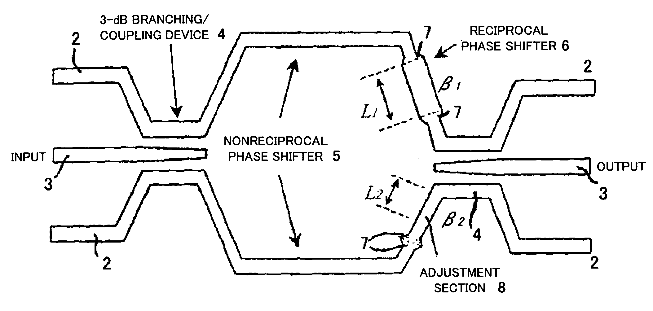
[0091]The layer structure of the waveguide is air (upper clad) / Ce:YIG (waveguide layer) / NOG (lower clad). In order to minimize the wavelength-dependence of the backward propagating waves, the reciprocal phase shifter 6 shown in FIG. 9 is formed in which L1=10.0 [μm]...

embodiment-2

[0094]Band broadening in a waveguide-type optical isolator having a waveguide layer comprising “Si”, as shown in FIG. 22, will now be described as Embodiment-2.

[0095]The layer structure of the present waveguide-type optical isolator is Ce:YIG (upper clad) / Si (waveguide layer) / SiO2 (lower clad layer). For the wavelength-dependence of the Faraday rotation coefficient of the upper clad Ce:YIG, “Ce:YIG” having the above-described value using FIG. 11 is used, for the wavelength-dependence of the refractive index of the waveguide layer Si, “Si” having a value shown in FIG. 23 is used, and for the wavelength-dependence of the refractive index of the substrate SiO2, “SiO2” having a value shown in FIG. 16 is used. The present waveguide-type optical isolator is an example of an ultra-small optical isolator formed from an SOI-wafer (Si / SiO2 / Si), and is used as an optical isolator for use in silicon-photonics optical circuits. In FIG. 22, although a multimode interference coupling device (an MM...

embodiment-3

[0099]A characteristic of a waveguide-type broadband optical isolator having a central wavelength of 1.55 [μm] is shown. The waveguide structure of which is shown in FIG. 14, in which L1=900 [μm], L2=899.55 [μm], W1=2.4 [μm], W2=2.0 [μm] and Lt=10 [μm]. The wavelength-dependence of the loss of a light wave entering the waveguide-type optical isolator obtained by the above design is shown in FIG. 26. The loss amount for the backward propagating waves is indicated by a solid line, while the loss amount for the forward propagating waves is indicated by a broken line. Over the wavelengths in the range of 1.4 [μm] to 1.65 [μm], the backward loss remarkably exceeds 30 [dB], which is a value conventionally required. As the deviation of the wavelength of incident light from 1.55 [μm] increases, the forward loss increases, but the wavelength-dependence of an isolation ratio defined by “backward loss−forward loss” is approximately determined by the wavelength-dependence of the backward loss, ...


PUM


Abstract

A waveguide-type broadband optical isolator according to the present invention, comprising: a reciprocal phase shifter which makes a phase difference 3π / 2 between a first light wave propagating through a first waveguide and a second light wave propagating through a second waveguide, with a fundamental operating wavelength λ, and a nonreciprocal phase shifter which provides a phase difference π / 2 for forward propagating waves and a phase difference −π / 2 for backward propagating waves.

Description

[0001]This application is a U.S. National Phase Application under 35 USC 371 of International Application PCT / JP2006 / 320521 filed Oct. 10, 2006.TECHNICAL FIELD[0002]The present invention relates to a waveguide-type broadband optical isolator, and in particular to a waveguide-type broadband optical isolator which has a remarkably broadened a wavelength range within which it operates with desired characteristics satisfied, and operates also on two wavelengths of a 1.31-μm band and a 1.55-μm band used in a long-distance optical fiber communication.BACKGROUND ART[0003]An optical isolator is a device which allows a light to pass through it in one direction only and blocks the light which attempts to propagate in the opposite direction. For example, by arranging an optical isolator on an exit end of a semiconductor laser, a light emitted from the semiconductor laser passes through the optical isolator and can be used as a light source for an optical fiber communication. Conversely, a ligh...

Claims


Application Information

Patent Timeline
Patent Type & Authority Patents(United States)
IPC IPC(8): G02B6/00
CPCG02F1/0955G02B2006/12159G02F1/225G02F1/3132G02F2203/04G02F2203/20G02B6/12G02B6/122G02B27/28
Inventor MIZUMOTO, TETSUYASHOJI, YUYA
Owner MITSUMI ELECTRIC CO LTD
Why Eureka
Try Eureka