Method for operating an internal combustion engine and device for implementing the method

a technology of internal combustion engine and method, which is applied in the direction of engines, machines/engines, mechanical equipment, etc., can solve the problems of reducing performance, and affecting the operation of the internal combustion engin

Active Publication Date: 2010-02-23
ROBERT BOSCH GMBH
View PDF9 Cites 8 Cited by
  • Summary
  • Abstract
  • Description
  • Claims
  • Application Information

AI Technical Summary

Benefits of technology

[0007]Due to the diagnosis of the reagent pressure the procedure according to the present invention considerably increases the safety during operation of the internal combustion engine, in particular if the reagent, such as fuel, is highly flammable. The procedure according to the present invention allows the detection of a leak in the reagent path. Furthermore, it is possible to check the valves disposed in the reagent path, which may jam in case of a fault.
[0009]In a further refinement of the example embodiment, it is checked whether the reagent pressure corresponds at least approximately to the reagent source pressure following a subsequent opening of the reagent safety valve. This makes it possible to detect jamming of the reagent safety valve in the closed state. Moreover, it can be detected that the reagent dosing valve jams in an at least partially open state.
[0011]According to one refinement, it is checked whether the reagent pressure is just below the reagent source pressure, minus the pressure drop at the reagent safety valve, when the reagent safety valve and the reagent dosing valve are open simultaneously. This measure makes it possible to determine whether either the reagent safety valve or the reagent dosing valve is jamming in the closed state.

Problems solved by technology

A defect of at least one of the pressure sensors may cause reduced performance of the SCR catalyst with the result that non-purified exhaust gas may reach the environment.
Moreover, it can be detected that the reagent dosing valve jams in an at least partially open state.

Method used


Image

  • Method for operating an internal combustion engine and device for implementing the method
  • Method for operating an internal combustion engine and device for implementing the method
  • Method for operating an internal combustion engine and device for implementing the method

Examples


Embodiment Construction

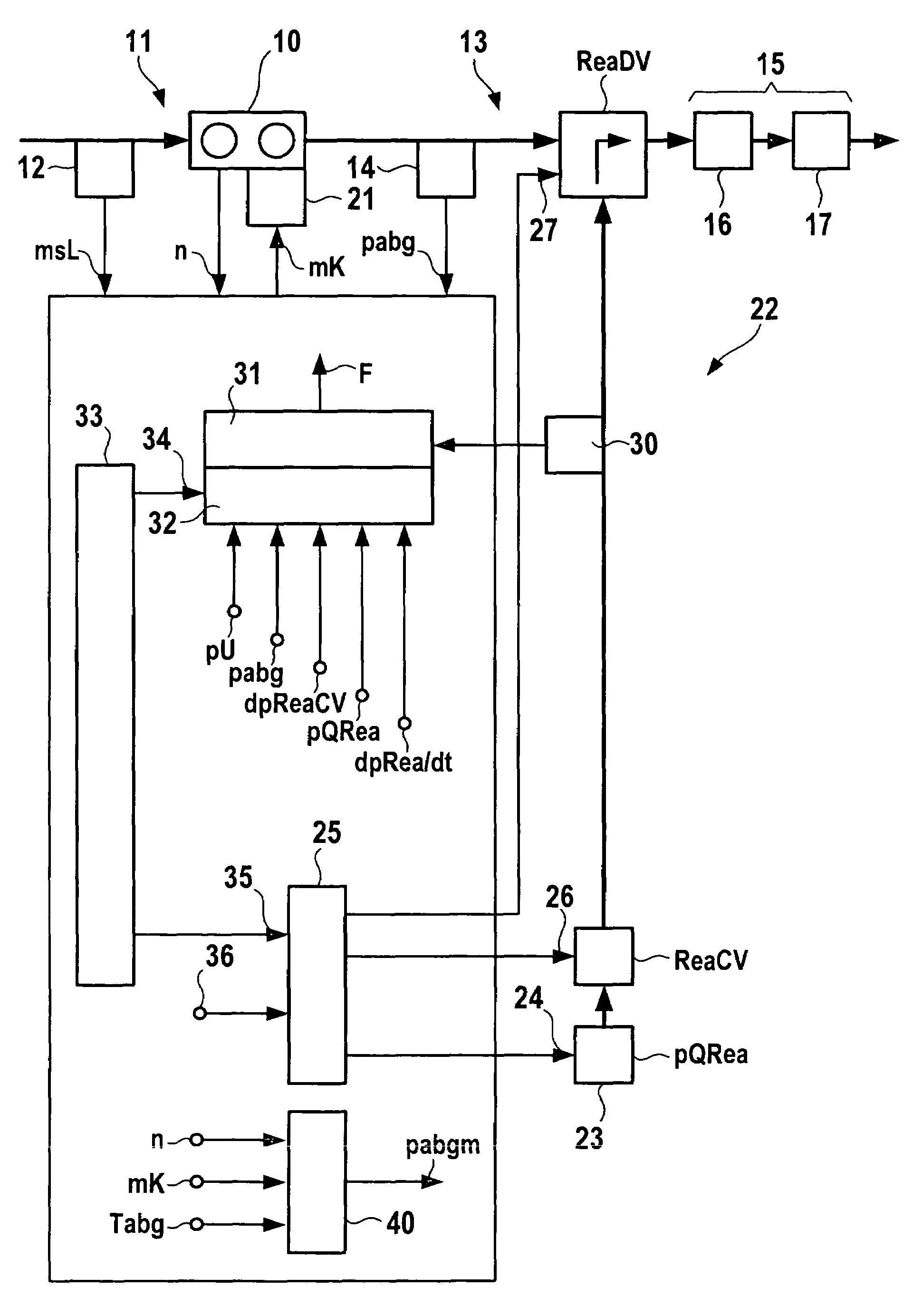
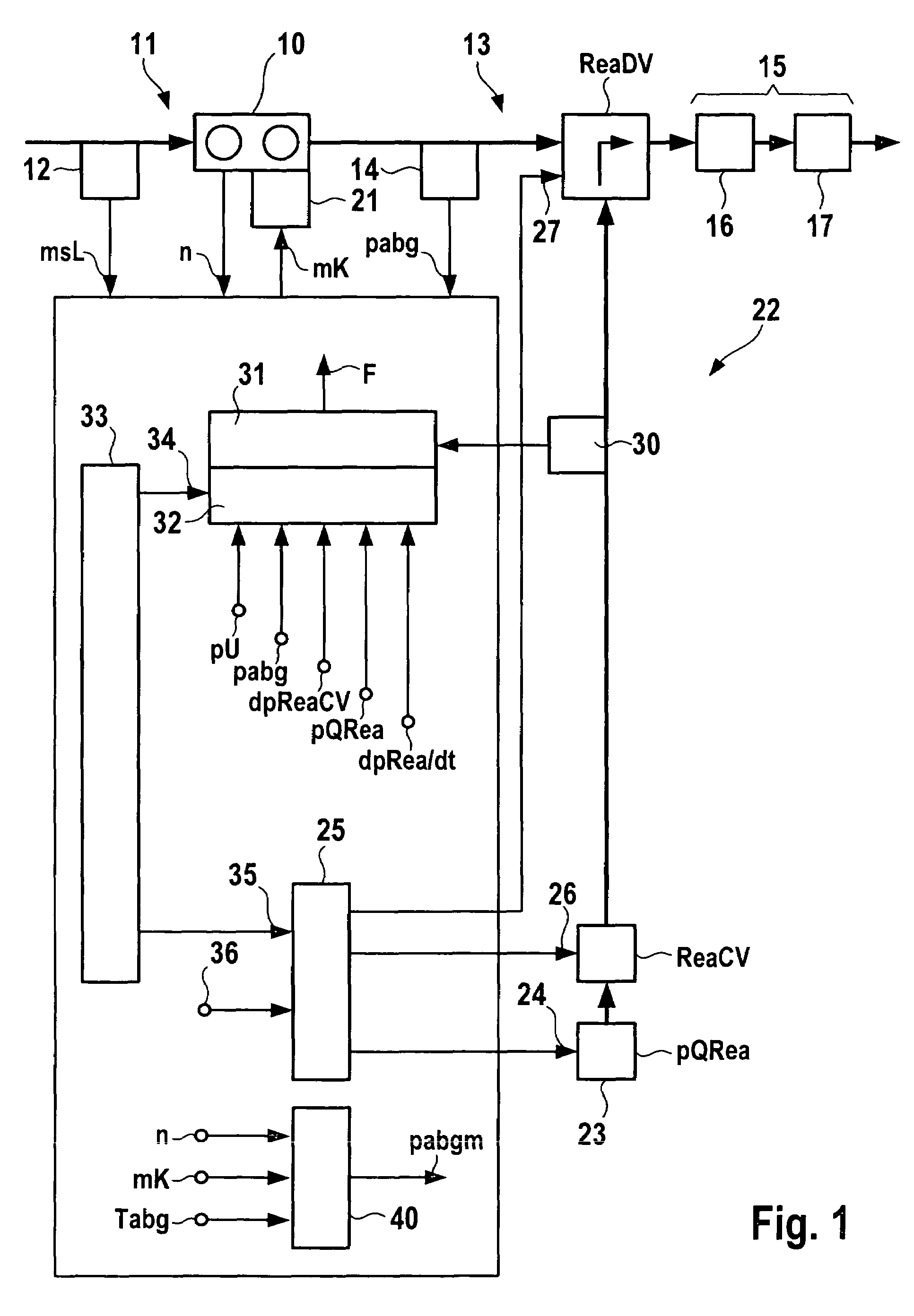
[0019]FIG. 1 shows an internal combustion engine 10 in whose air-induction region 11 an inducted-air detection 12 is located and in whose exhaust-gas region 13 an exhaust-gas pressure sensor 14, a reagent dosing valve ReaDV, and an exhaust-gas treatment device 15 are positioned. Exhaust-gas treatment device 15 includes a first and a second exhaust-gas treatment device 16, 17, respectively.

[0020]Inducted-air detection 12 outputs an air signal msL to a control unit 20; internal combustion engine 10 supplies rotational speed n, and exhaust pressure sensor 14 supplies an exhaust-gas pressure signal pabg.

[0021]Control unit 20 sends a fuel signal mK to a fuel-metering device 21.

[0022]In a reagent path 22 a reagent pump 23 brings a reagent to a predefined reagent source pressure pQRea. Reagent pump 23 is triggered by a reagent pump trigger signal 24, which is provided by a reagent dosage controller 25 situated in control unit 20.

[0023]The reagent arrives at a reagent safety valve ReaCV, wh...


PUM


Abstract

A method is provided for operating an internal combustion engine in whose exhaust-gas region an exhaust-gas treatment device is situated, and in which a reagent is introduced into the exhaust-gas region of the internal combustion engine. in addition, a device is provided for implementing the method. The reagent pressure occurring between a reagent safety valve and a reagent dosing valve, disposed directly in the exhaust-gas region is recorded during different states of the reagent safety valve and / or the reagent dosing valve and compared to at least one threshold value. If the threshold is exceeded, a fault signal is provided. This may offer high safety which may be of particular importance when fuel is used as reagent.

Description

FIELD OF THE INVENTION[0001]The present invention relates to a method and a device for operating an internal combustion engine in whose exhaust region an exhaust-treatment device is disposed and in which a reagent is introduced into the exhaust region upstream from the exhaust-treatment device.BACKGROUND INFORMATION[0002]In German Patent Application No. DE 10 2004 018 221 A1, a method and a device are described in which a pressurized reagent is sprayed into the exhaust gas of an internal combustion engine in front of an SCR catalyst. The reagent pressure is specified to a predefined reagent setpoint pressure as a function of a characteristic quantity. A performance quantity of the internal combustion engine and / or a characteristic quantity of the exhaust gas of the internal combustion engine can be utilized as characteristic quantity. The predefined reagent setpoint pressure is regulated within the framework of a closed-loop control in which the actual reagent pressure is detected b...

Claims


Application Information

Patent Timeline
Patent Type & Authority Patents(United States)
IPC IPC(8): F01N3/00
CPCF01N3/0253F01N3/0871F01N11/00F01N2550/05F01N2560/08F01N2610/1493F01N2900/1808Y02T10/47Y02T10/40
Inventor PFAEFFLE, ANDREASSCHALLER, JOHANNESVEIGEL, WOLFRAMSCHARSACK, CORDDREFS, RUDIPAULI, VIKTORWALTER, THOMAS EH
Owner ROBERT BOSCH GMBH
Why Eureka
Try Eureka