Method and apparatus for rapid automatic engagement of a probe

a technology of automatic engagement and probe, applied in the direction of mechanical roughness/irregularity measurement, instruments, measurement devices, etc., can solve the problem of reducing separation and achieve the effect of reducing the engagement time and minimal processing

Active Publication Date: 2010-02-23
BRUKER NANO INC
View PDF17 Cites 15 Cited by
  • Summary
  • Abstract
  • Description
  • Claims
  • Application Information

AI Technical Summary

Benefits of technology

[0021]A preferred embodiment of the invention overcomes the above-noted drawbacks using unique control architecture which continuously monitors probe-sample separation based on probe-sample interaction to reduce engage times from more than 10 seconds to less than 5 seconds. In particular, the center of the engage control resides with a system processor (e.g., a DSP of a host computer) which communicates information regarding probe-sample interaction in parallel with other AFM instructions, and minimal processing by the host software. As a result, control signals based on probe-sample interaction can be transmitted to a motion controller in substantially real-time.

Problems solved by technology

In addition, the first reducing step generally continuously reduces the separation.

Method used


Image

  • Method and apparatus for rapid automatic engagement of a probe
  • Method and apparatus for rapid automatic engagement of a probe
  • Method and apparatus for rapid automatic engagement of a probe

Examples


Embodiment Construction

[0070]The invention as described herein is applicable to virtually any probe based instrument in which the probe / sample spacing must be reduced prior to obtaining sample characteristic measurements. These instruments include SPMs such as AFMs, tunneling force microscopes, and lateral force microscopes. Hence, while the invention will be described primarily in conjunction AFMs by way of example, it is to be understood that it is applicable to many other probe based instruments is well.

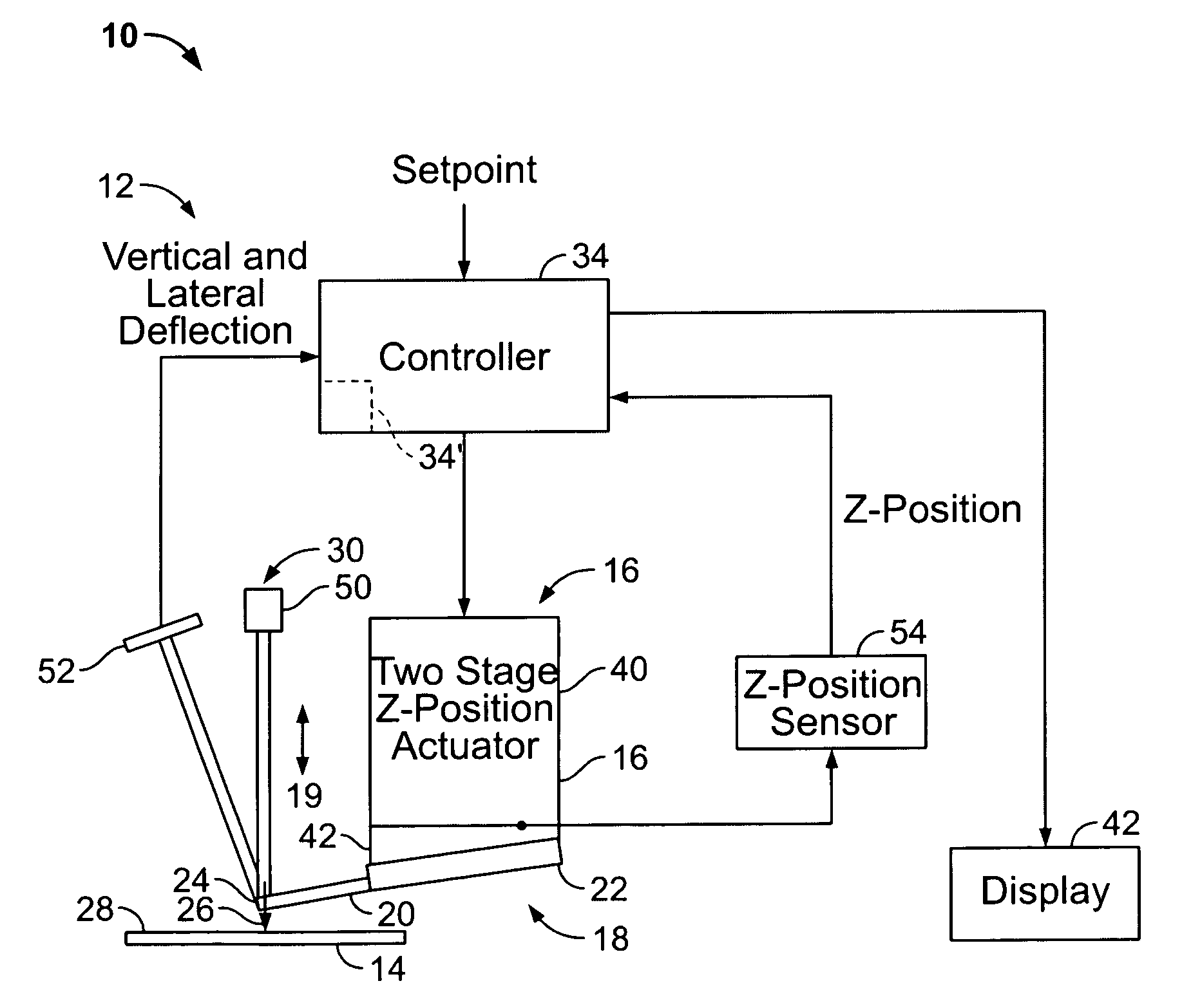
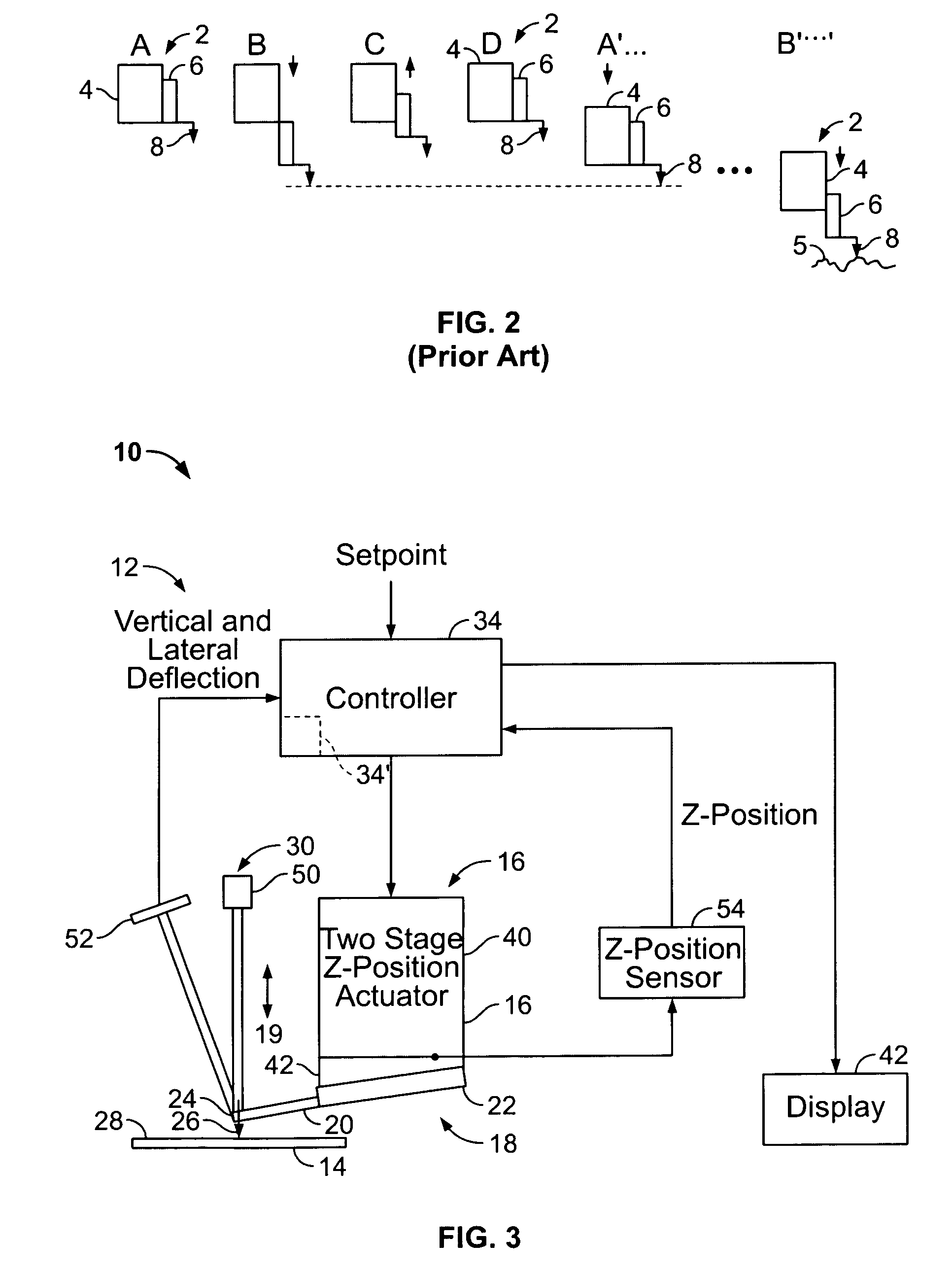
[0071]Referring to FIG. 3, a typical AFM 10 has a probe assembly 18 including a probe 19 configured to interact with a sample 14. Probe 19 includes a cantilever 20 having a tip 26 that interacts with sample 14. Probe assembly 18 includes a fixed end or base 22 preferably mounted to an AFM probe holder (not shown), while a free, distal end 24 of cantilever 20 supports tip 26. AFM 10 also includes a feedback loop 12 to control an AFM Z position actuator 16 or simply “Z actuator”.

[0072]In operation, the in...


PUM


Abstract

A method and apparatus of engaging a probe with a sample surface including automatically reducing the spacing between a probe of a probe based instrument and a sample from an initial separation to one in which the probe is positioned for obtaining a sample surface measurement in less than ten seconds without damaging either the probe or the sample. The method includes oscillating the probe, measuring at least one parameter of probe oscillation and then engaging the probe and the sample by generally continuously controlling the reducing step based on the measuring step to reduce the separation from an initial separation to an engage position. In addition to feeding back directly on the tip-sample interaction, a direct communication line is provided between the processor used to generate control signals that govern the engage and a conventional motion controller. In an alternative, a coarse positioning actuator and a fine positioning actuator in which the control of both is coordinated under feedback to place the probe in the engaged position, and wherein the close approach phase of the algorithm is controlled by a dedicated real time controller.

Description

CROSS REFERENCE TO RELATED APPLICATION[0001]This application is a continuation of U.S. patent application Ser. No. 11 / 104,283, filed on Apr. 12, 2005, now abandoned the entirety of which is expressly incorporated by reference herein.BACKGROUND OF THE INVENTION[0002]1. Field of the Invention[0003]The present invention is directed to metrology instruments employing a probe and, more particularly, relates to a method and apparatus for automatically and rapidly driving a probe of such an instrument into engagement with a sample.[0004]2. Description of Related Art[0005]Several probe-based instruments monitor the interaction between a probe and a sample to obtain information concerning one or more characteristics of the sample. For example, scanning probe microscopes (SPMs) typically characterize the surface of a sample down to atomic dimensions by monitoring the interaction between the sample and a tip on the cantilever probe. By providing relative scanning movement between the probe and...

Claims


Application Information

Patent Timeline
Patent Type & Authority Patents(United States)
IPC IPC(8): G01Q10/00G01Q60/24
CPCB82Y35/00G01Q10/065
Inventor MININNI, PAUL I.OSBORNE, JASON R.YOUNG, JAMES M.MEYER, CHARLES R.
Owner BRUKER NANO INC
Why Eureka
Try Eureka