Defined leak path for high pressure seal

a leak path and high pressure technology, applied in the direction of hose connection, positive displacement liquid engine, liquid fuel engine, etc., can solve the problems of over-expensive wear and damage of these components

Active Publication Date: 2010-02-23
WATERS TECH CORP
View PDF5 Cites 12 Cited by
  • Summary
  • Abstract
  • Description
  • Claims
  • Application Information

AI Technical Summary

Benefits of technology

[0018]The passage means may take several forms. For example, the passage means may comprise a channel in at least one of the housing or cap. Or, the passage means may be incorporated in the seal. A preferred seal has a flexible section and a seal compression pad. The flexible section is for engaging the housing engagement surface. The seal compression pad has less flexibility than the flexible section to compress said flexible section against said seal compression surface. A channel is provided in the seal compression pad to direct fluids to the exterior of the housing or cap. Where the housing is a pump or valve housing, embodiments of the present invention prevent major damage in the event seals leak.
[0021]Embodiments of the present invention provide a defined path for fluids which leak past seal surfaces and prevent the build up of pressure between parts of pumps and valve assemblies. This build up of pressure can result is miss-aligned parts and components which parts and components may be subject to stresses which they can not withstand or result in wear.

Problems solved by technology

This misalignment can lead to undue expensive wear and damage to the these components.

Method used


Image

  • Defined leak path for high pressure seal
  • Defined leak path for high pressure seal
  • Defined leak path for high pressure seal

Examples


Embodiment Construction

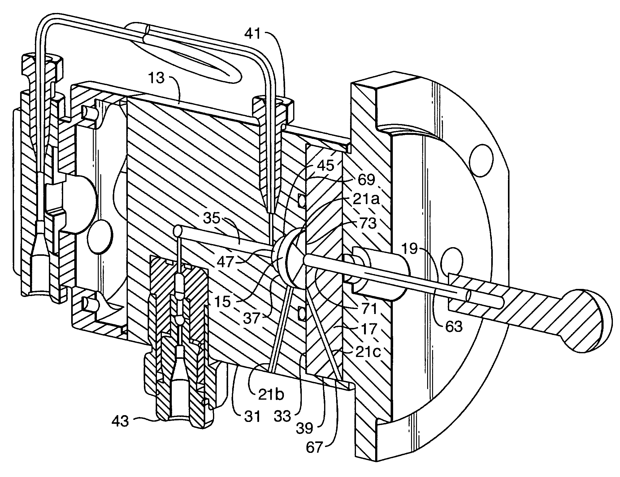
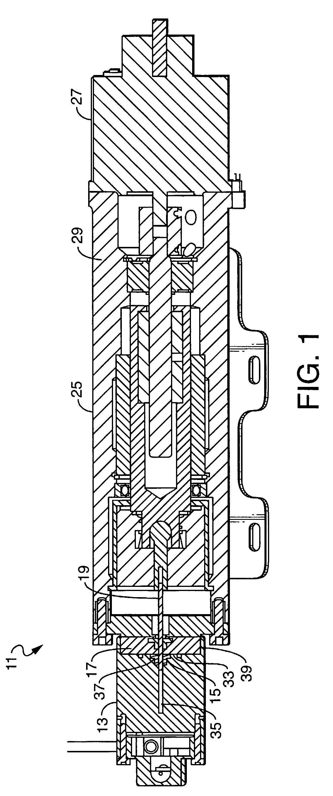
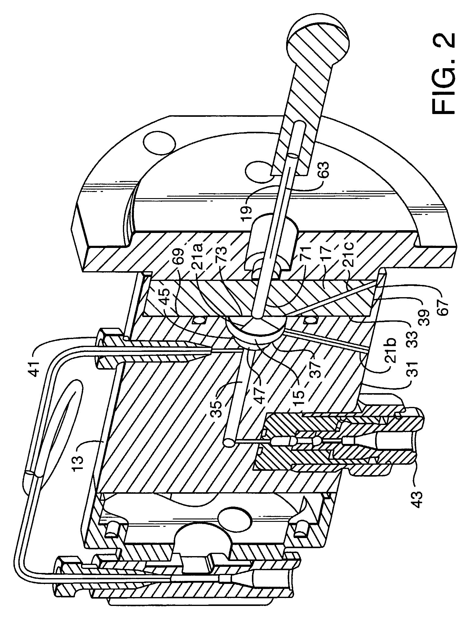
[0027]Embodiments of the present invention will now be described with respect to the Figures with the understanding that the embodiments described are preferred embodiments. For example, without limitation, the following discussion will describe a pump assembly with the understanding that the invention applies to valves and other fittings as well.

[0028]Turning now to FIG. 1, a device, in the form of a pump, generally designated by the numeral 11 is depicted. The device 11 has a housing 13, a seal 15, a cap 17, shaft 19 and passage means 21a, 21b, and 21c as best seen in FIG. 2. Returning now to FIG. 1, device 11, as a pump, produces fluids under pressure. However, features of device 11 may be modified such that the device could direct fluids to different fluid paths in the nature of a valve or fitting.

[0029]The housing 13 is part of a pump assembly 25 having a motor 27 and spindle mechanism 29. Those skilled in the art will recognize that housing 13 could be described as a housing f...


PUM


Abstract

Embodiments of the present invention are directed to methods and devices for conveying or containing fluids under pressure in which seals are provided with a defined path to vent fluid in the event of a seal failure.

Description

CROSS REFERENCE TO RELATED APPLICATIONS[0001]This application claims priority from U.S. Provisional Patent Application No. 60 / 602,376, filed Aug. 18, 2004. The contents of these applications are incorporated herein by reference.STATEMENT REGARDING FEDERALLY FUNDED RESEARCH AND DEVELOPMENT[0002]N / AFIELD OF INVENTION[0003]The present invention relates to the field of fluid handling devices.BACKGROUND OF THE INVENTION[0004]The present invention is directed to devices for handling fluids under pressure. For example, without limitation, embodiments of the present invention have application for pumps and valves that produce or control fluids under pressure. Devices for handling high pressures are built with parts and components with closely controlled tolerances. Such parts and components are also expensive to manufacture. It is desirable to be able to design components and parts which exhibit wear such that the worn parts and components can be replaced. And, it is desirable to reuse part...

Claims


Application Information

Patent Timeline
Patent Type & Authority Patents(United States)
IPC IPC(8): F16L35/00
CPCF04B53/04F04B53/164F16J15/004Y10T137/0452Y10T137/5762Y10T137/9247F04B39/00F16K11/0716F16J15/16F16K41/00
Inventor ANGELOSANTO, JOHNLUONGO, JOSEPH A.RUBINO, FRANK A.
Owner WATERS TECH CORP
Why Eureka
Try Eureka