Catheter with adjustable deflection

a catheter and deflection technology, applied in the field of ep catheters, can solve the problems of inconvenient use, inconvenient use, and inconvenient use, and achieve the effects of reducing the number of catheters

Active Publication Date: 2016-11-24
BIOSENSE WEBSTER (ISRAEL) LTD
View PDF10 Cites 13 Cited by
  • Summary
  • Abstract
  • Description
  • Claims
  • Application Information

AI Technical Summary

Benefits of technology

[0007]The present invention is directed to a catheter with a catheter shaft that has a more uniform construction throughout its length, including an elongated proximal section and a distal deflection section, and a catheter shaft that can adopt more than one deflection curvature. The catheter shaft includes a flexible outer tubular member, and a less flexible inner tubular member extending through the outer tubular member in the elongated proximal section of the catheter shaft, wherein the inner tubular member is afforded longitudinal movement relative to the outer tubular member. The catheter also includes at least one puller wire extending through the inner tubular member to deflect the distal deflection section of the catheter shaft, wherein longitudinal movement of the inner tubular member relative to the outer tubular member enables an operator to select and set a deflection curvature of the distal deflection section.

Problems solved by technology

The catheter is therefore a composite of different constructions and materials and consequently may not have uniform characteristics in flexibility, torsional stiffness, pushability and / or rotational accuracy.
Assembling puller wires and their respective compression coils, feeding distal portion of the puller wires through their dedicated lumens, and connecting the two structures all require extensive skilled manual labor.
Moreover, inner walls of multi-lumened tubing occupy precious space within a catheter.

Method used


Image

  • Catheter with adjustable deflection
  • Catheter with adjustable deflection
  • Catheter with adjustable deflection

Examples


Embodiment Construction

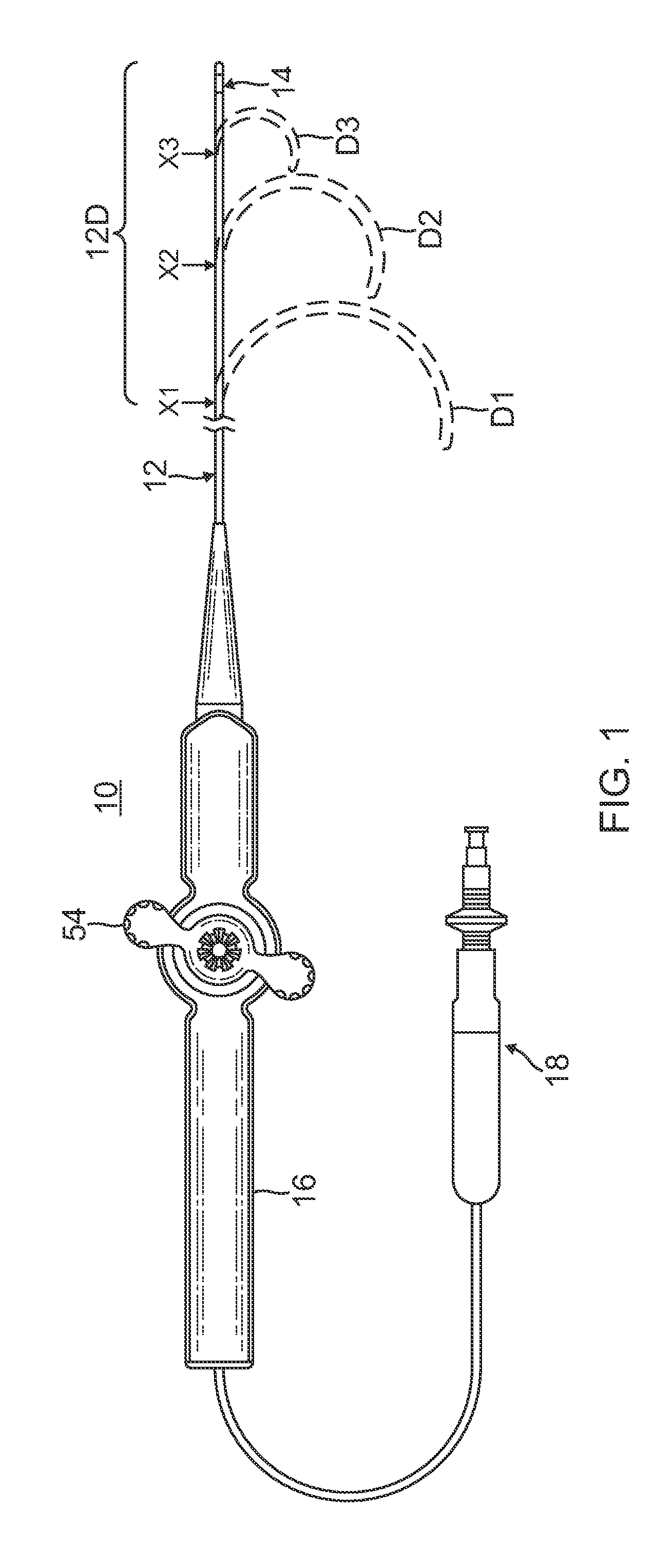
[0031]As shown in FIG. 1, a catheter 10 comprises an elongated catheter shaft 12, a distal section 14 with a distal tip electrode 15, a deflection rocker handle 16 attached to the proximal end of the catheter shaft 12 and a deflection curvature adjustment handle 18 proximal of the deflection rocker handle 16. In accordance with a feature of the present invention, the elongated catheter shaft 12 has an adjustable deflection section 12D which allows an operator user to vary and select the deflection curvature, as needed or desired, between multiple deflection curvatures, for example, D1, D2 and D3.

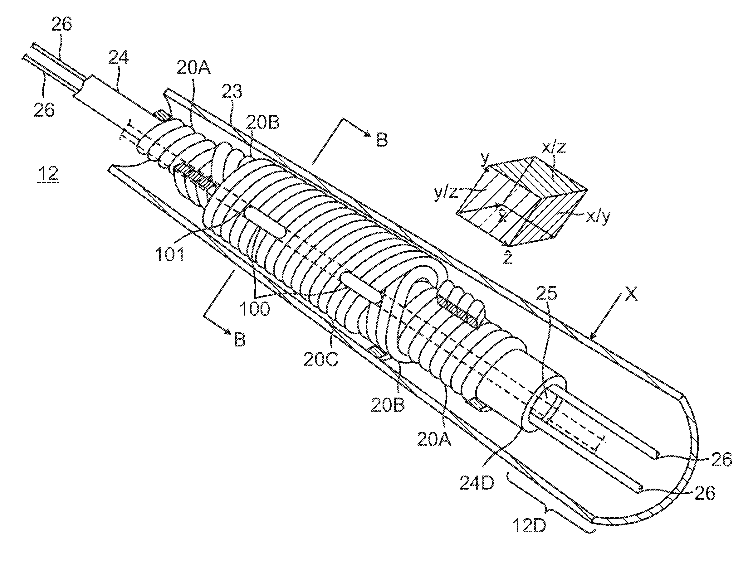
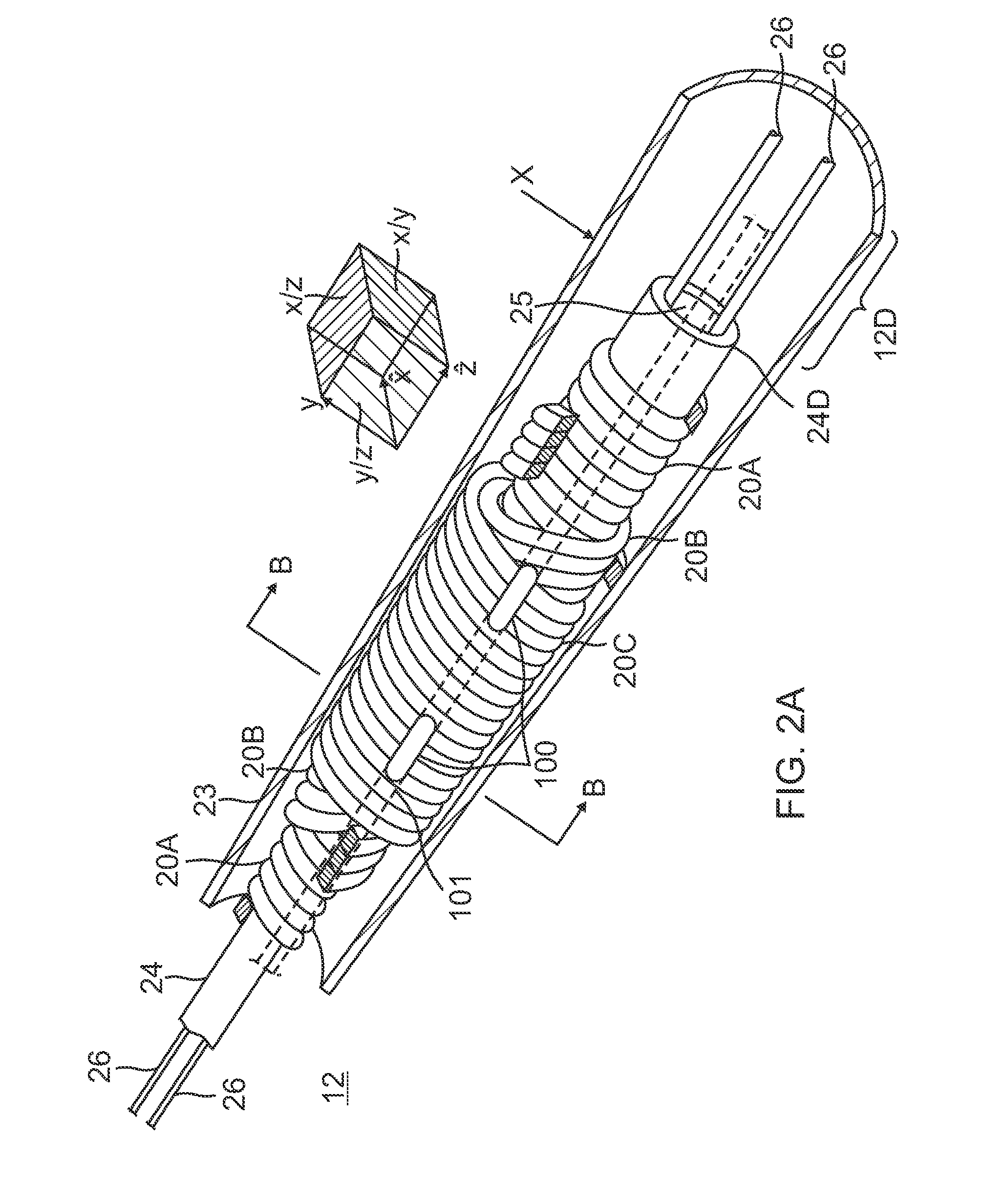
[0032]With reference to FIGS. 2A and 2B, the catheter shaft 12 comprises an elongated tubular construction having a single, axial or central lumen 18. The catheter shaft 12 is flexible, i.e., bendable, but substantially non-compressible along its length. The catheter shaft 12 can be of any suitable construction and made of any suitable material. In some embodiments, the catheter shaft 12 com...


PUM


Abstract

A catheter having a catheter shaft that has a more uniform construction throughout its length and is able to provide more than one deflection curvature. The catheter shaft includes a flexible outer tubular member, and a less flexible inner tubular member extending through the outer tubular member in a proximal section of the catheter shaft, wherein the inner tubular member is afforded longitudinal movement relative to the outer tubular member. The catheter also includes at least one puller wire extending through the inner tubular member to deflect a distal deflection section of the catheter shaft, wherein longitudinal movement of the inner tubular member relative to the outer tubular member enables an operator to select and set a deflection curvature of the distal deflection section.

Description

FIELD OF INVENTION[0001]This invention relates to electrophysiologic (EP) catheters, in particular, deflectable EP catheters for mapping and / or ablation in the heart.BACKGROUND[0002]Electrode catheters have been in common use in medical practice for many years. They are used to stimulate and map electrical activity in the heart and to ablate sites of aberrant electrical activity.[0003]In use, the electrode catheter is inserted into a major vein or artery, e.g., femoral vein, and then guided into the chamber of the heart which is of concern. Within the heart, the ability to control the exact position and orientation of the catheter tip is critical and largely determines how useful the catheter is.[0004]Steerable (or deflectable) catheters are generally well-known. A typical catheter has an elongated catheter body, an intermediate deflection section and a distal tip section. The elongated catheter body extends through the patient's vasculature and the shorter intermediate deflection i...

Claims


Application Information

Patent Timeline
Patent Type & Authority Applications(United States)
IPC IPC(8): A61M25/01A61B5/296
CPCA61M25/0147A61M2025/0004A61B2018/00577A61B5/042A61M25/0023A61B18/1492A61M25/0082A61B2018/00642A61B2018/00267A61B2018/00351A61B2018/1467A61B2562/0209A61B2562/04A61M2025/015A61B5/287A61M25/0141A61M25/0144A61M2025/0161A61M25/0136A61M25/0054A61M2025/0175
Inventor BEECKLER, CHRISTOPHER THOMASHETTEL, ROWAN OLUND
Owner BIOSENSE WEBSTER (ISRAEL) LTD
Why Eureka
Try Eureka